Control device for a three-phase rotating machine

A technology for rotating machinery and control equipment, applied in torque ripple control, motor generator control, AC motor control, etc., can solve problems such as thermal characteristic deterioration, torque fluctuation, etc., to suppress the influence of current stress and reduce sound and/or vibration effects

Active Publication Date: 2013-10-30
DENSO CORP
View PDF7 Cites 15 Cited by
  • Summary
  • Abstract
  • Description
  • Claims
  • Application Information

AI Technical Summary

Problems solved by technology

Current difference may cause torque ripple and degrade thermal characteristics (especially, during low speed rotation)

Method used


Image

  • Control device for a three-phase rotating machine
  • Control device for a three-phase rotating machine
  • Control device for a three-phase rotating machine

Examples


no. 1 example

[0042] will refer to Figure 1-16 A first embodiment of the present disclosure is described.

[0043] [Structure of control equipment for three-phase rotating machinery]

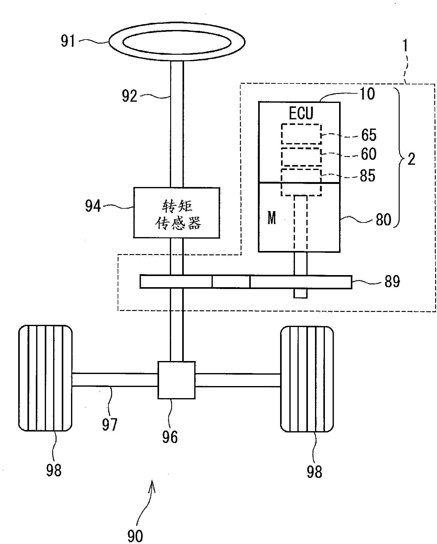
[0044] figure 2 The entire structure of a steering system 90 including the electric power steering apparatus 1 is shown. A steered wheel 91 is secured to the top of a steering shaft 92, which is provided with a torque sensor 94 which senses the steering torque of the shaft. The bottom of the steering shaft 92 has a pinion 96 that meshes with a rack 97 . A pair of wheels 98 are rotatably connected to both ends of the rack gear 97 via tie rods or the like. Pinion 96 converts rotational motion of steering shaft 92 into linear motion of rack gear 97 . The steering device 1 steers the pair of wheels 98 by an angle according to the linear displacement of the rack 97 .

[0045] The steering device 1 includes an actuator 2 and a reduction gear 89 . The actuator 2 rotates the rotary shaft. The gear 89 reduce...

no. 2 example

[0190] exist Figure 17 In the second embodiment shown in , the difference / sum gain ratio α is a constant value αL in the low frequency range ZL where the reference frequency fr is lower than the threshold value frt, and is a constant value αL in the high frequency range where the reference frequency fr is equal to or higher than the threshold value frt In ZH, the ratio α varies with the reference frequency fr. The reference frequency threshold frt is equivalent to the frequency at which the stress component of the induced voltage of the motor 80 is equal to or greater than a predetermined value in the high frequency range ZH.

[0191] In the low frequency range ZL where the motor 80 rotates at a relatively low speed, the stress component of the induced voltage is on an order that it does not cause a problem. It is therefore desirable to fix the difference / sum gain ratio α at an optimum value that limits overcurrent in one of the first and second units if the other fails.

...

no. 3 example

[0194] exist Figure 18 In the third embodiment shown, in the low frequency range ZL where the reference frequency fr is lower than the threshold value frt, the difference / sum gain ratio α is a constant value αL, and in the high frequency range where the reference frequency fr is equal to or higher than the threshold value frt In ZH, the difference / sum gain ratio α is a constant value αH smaller than the value αL.

[0195] The ECU 10 uniformly uses the difference / sum gain ratio αH suitable for the actually assumed highest frequency fr over the entire high frequency range ZH where the motor 80 rotates at a relatively high speed and the influence of the stress component must be suppressed. Therefore, the relationship between the reference frequency fr and the difference / sum gain ratio α is shown in two stages. This makes setup simpler than alpha.

[0196] In a modification (not shown) of the third embodiment, the high-frequency range ZH in which the reference frequency fr is e...


PUM


Abstract

In a control device for a three-phase rotating machine with first and second winding sets, a current feedback computing section includes a current sum controller and a current difference controller. The current sum controller multiplies, by a sum gain, an error between a sum of current command values for alternating currents output from first and second inverters and a sum of sensed current values and computes a sum of voltage command values. The current difference controller multiplies, by a difference gain, an error between a difference of the current command values and a difference between the sensed current values, and computes a difference of voltage command values. In a variable-responsiveness mode, a gain ratio between the sum gain and the difference gain is varied according to a reference frequency such that the current sum controller and the current different controller are different in responsiveness.

Description

technical field [0001] The present disclosure relates to a control device for a three-phase rotating machine. Background technique [0002] A known control device for controlling the drive of a three-phase rotating machine with two sets of three-phase windings comprises a power converter for one unit and a power converter for the other unit. Each power converter is associated with a corresponding one of the winding sets. [0003] For example, Patent Document 1 (JP-A-2011-152027) discloses a control device including a power converter in one unit and a power converter in another unit. Each power converter supplies current to a corresponding one of the two sets of windings of the three-phase motor. The control device performs feedback control of the sum of currents supplied from the two power converters to the corresponding two winding sets. [0004] The control device may only control the sum of the currents output from the two power converters. In this case, if two cells ...

Claims


Application Information

Patent Timeline
Patent Type & Authority Applications(China)
IPC IPC(8): H02P21/05H02P27/06B62D5/04B62D6/00H02P21/22H02P23/04H02P27/08
CPCH02P25/22H02P6/10H02P21/22
Inventor 铃木崇志
Owner DENSO CORP
Why Eureka
Try Eureka