Concentric bidirectional-rotation feed stirring machine

A two-way rotation, mixer technology, applied in mixer accessories, mixers with rotating containers, mixers and other directions, can solve the problems of low mixing efficiency, incomplete discharge, and layered feed mixing, and achieves simple structure and feeding. Convenience and complete discharge

Inactive Publication Date: 2013-11-06
GANSU AGRI UNIV
View PDF5 Cites 4 Cited by
  • Summary
  • Abstract
  • Description
  • Claims
  • Application Information

AI Technical Summary

Problems solved by technology

Considering that the current feed mixer takes a long time to mix, the mixing efficiency is low, and the feed mixing is layered and uneven. The separate design of the feed inlet and outlet of the mixer occupies the inner space of the mixing drum, and the positions of the feed inlet and outlet are fixed. , inconvenient feeding, incomplete discharge, etc., a feed mixer with two sets of motors driving the stirring shaft and the mixing drum coaxial and bidirectional rotation was proposed.

Method used


Image

  • Concentric bidirectional-rotation feed stirring machine
  • Concentric bidirectional-rotation feed stirring machine
  • Concentric bidirectional-rotation feed stirring machine

Examples


Embodiment 1

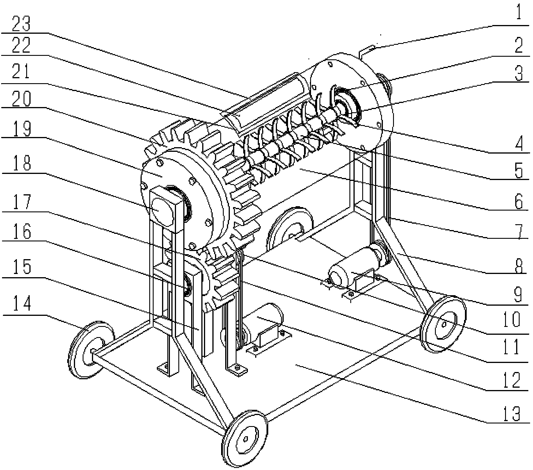
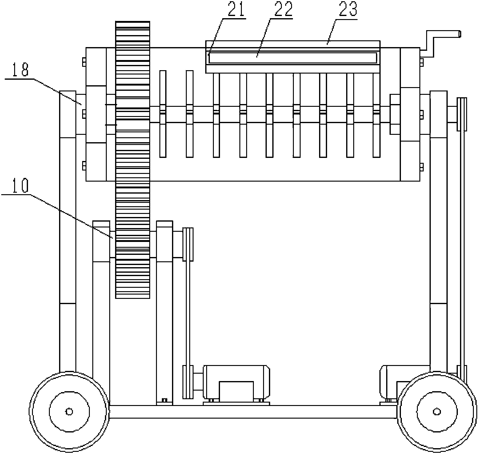
[0020] Embodiment 1: see figure 1 , figure 2 , image 3 , Figure 4 , Figure 5 , a coaxial two-way rotating feed mixer, including a mixing shaft 5 in the mixing drum 6, the mixing drum 6 is set on the support shaft 18 through the large bearing 2, and the mixing drum 6 is provided with a mixing drum on both sides The end cover 19; the stirring shaft 5 is driven by the motor I9 through the transmission belt I7, and the stirring shaft 5 is set on the supporting shaft 18 through the small bearing 3; The gear transmission shaft 10 is fixedly connected, driven by the motor II 12 through the transmission belt II 11 , and the gear transmission shaft 10 is arranged on the gear transmission shaft supporting frame 15 through the bearing 16 .

[0021] The mixing drum 6 is provided with a feed / discharge port 22, and the feed port and the discharge port share the same port.

[0022] Described feed / discharge port 22 is provided with feed / discharge port cover 21, and feed / discharge por...

Embodiment 2

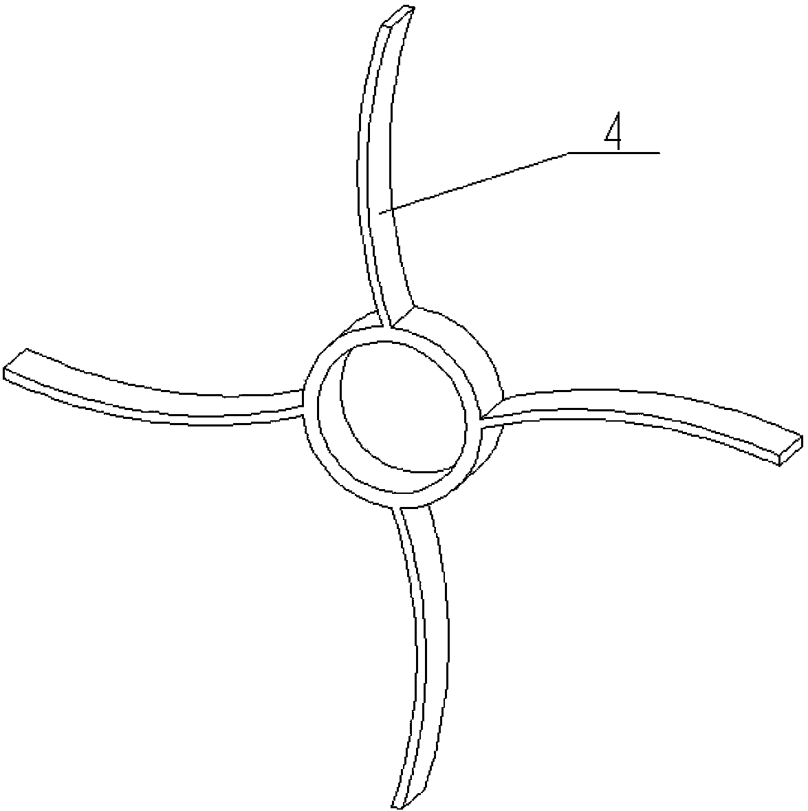
[0026] Embodiment 2: see figure 1 , figure 2 , image 3 , Figure 4 Four arc-shaped blades are welded on the stirring blade 4, the width of each blade is 150-200mm, the large bearing 2, the small bearing 3 and the bearing 16 are roller bearings, and the diameter of the mixing drum 6 is 1.1-1.3m. The optimum ratio of the diameter of the mixing drum 6 to the diameter of the stirring shaft 5 should be 3-4. The overall dimensions of the mixer are about: 4.0-4.5m in length; 1.8-2.0m in width; 1.7-1.9m in height. 6 The capacity is 7-11m 3 , the best amount of feed in the mixing drum 6 is 40%-55% of its capacity, that is, the best filling factor of the mixing drum 6 is 0.40-0.55, and the rotating speed of the stirring shaft 5 should be 2.2-55% of the rotating speed of the mixing drum 6. 2.5 times, the rotating speed of the stirring shaft 5 is 50-60 rpm, the rotating speed of the mixing drum 6 is 20-30 rpm, the stirring time is about 2 minutes, and the unloading time is about 0.5...

Embodiment 3

[0036] Embodiment 3: see Figure 5 , a coaxial two-way rotating feed mixer, basically the same structure as Embodiment 1 and Example 2, the difference is that the middle of the mixing drum 6 is cylindrical, and the two ends are tapered. The volume of the mixing drum makes the discharge more smooth.

[0037] By adopting the above-mentioned embodiment, the concentric two-way rotating feed mixer of the present invention has good mobility, high mixing efficiency, uniform feed mixing, no layering, more convenient feeding, more thorough feeding, reduced labor intensity, and realized farm feed Stirring mechanization and automation.


PUM


Abstract

The invention mainly relates to a feed stirring machine, in particular to a concentric bidirectional-rotation feed stirring machine suitable for feed stirring operation of large farms. The concentric bidirectional-rotation feed stirring machine comprises a stirring shaft arranged in a stirring barrel and is characterized in that the stirring barrel is arranged on a support shaft through a large bearing, and two sides of the stirring barrel are provided with stirring barrel end covers. The stirring shaft is driven by an electric motor I through a driving belt I and arranged on the support shaft through a small bearing. The stirring barrel is fixedly connected with a gear ring, the gear ring is meshed with a gear, the gear is fixedly connected with a gear transmission shaft and driven by an electric motor II through a driving belt II, and the gear transmission shaft is arranged on a gear transmission shaft support frame through a bearing. The concentric bidirectional-rotation feed stirring machine has the advantages of being simple in structure and good in mobility, the stirring shaft and the stirring barrel form concentric retrograde rotation, and the disadvantages of long stirring time, low stirring efficiency, layered and even feed stirring and the like of a traditional feed stirring machine are overcome. A feeding port and a discharging port of the stirring machine are the same feeding/discharging port, so that an internal space of the stirring barrel is fully utilized. Feeding of the stirring machine is convenient and discharging of the stirring machine is thorough by turning a handle.

Description

Technical field: [0001] The invention mainly relates to agricultural machinery, and relates to a feed mixing machine, which is especially suitable for feed mixing operations in large farms. Background technique: [0002] Feed mixing is a necessary step for farms. The traditional way of mixing feed is manual mixing. However, this method is time-consuming and laborious, and has low work efficiency. It has been gradually eliminated in large-scale farms and replaced by feed mixers. The current feed mixers are roughly divided into two types, horizontal feed mixers and vertical feed mixers. However, whether it is a horizontal or vertical feed mixer, most of them use a set of motors to drive the stirring shaft and stirring blades to stir the feed. This single stirring method takes a long time and has low stirring efficiency. The problem of stratification in feed mixing, that is, the phenomenon of uneven feed mixing. At the same time, the feed inlet and outlet of the current feed ...

Claims


Application Information

Patent Timeline
Patent Type & Authority Applications(China)
IPC IPC(8): B01F9/08B01F15/02B01F29/64
Inventor 王松林韩正晟戴飞高爱民杨杰陆祥辉王跃涵
Owner GANSU AGRI UNIV
Why Eureka
Try Eureka