
Rotary compressor

A technology for rotary compressors and compression mechanisms, which is applied to rotary piston/oscillating piston pump components, mechanical equipment, machines/engines, etc. It can solve problems such as eccentric crankshaft and sliding plate wear, and prevent reliability reduction Effect

Inactive Publication Date: 2013-11-13
GUANGDONG MEIZHI COMPRESSOR
View PDF5 Cites 3 Cited by
  • Summary
  • Abstract
  • Description
  • Claims
  • Application Information

AI Technical Summary

Problems solved by technology

Therefore, it is easy to cause wear of the eccentric crankshaft and the sliding plate

Method used


Image

  • Rotary compressor
  • Rotary compressor
  • Rotary compressor

Examples


Embodiment 1

[0025] As Embodiment 1 of the present invention, technical disclosure is made based on a rotary compressor, which is a typical representative model of rotary compressors.

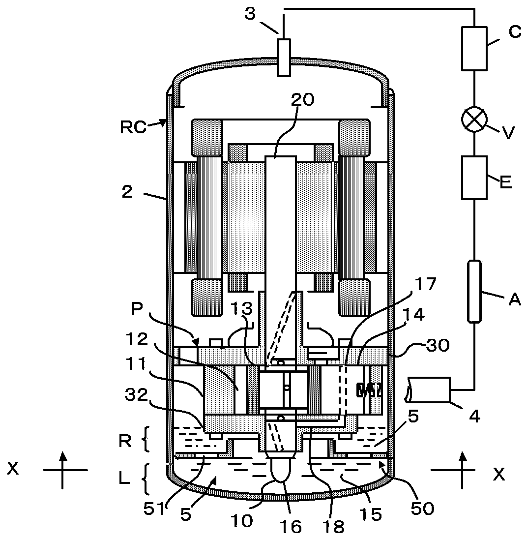
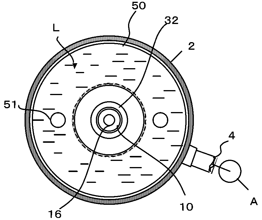
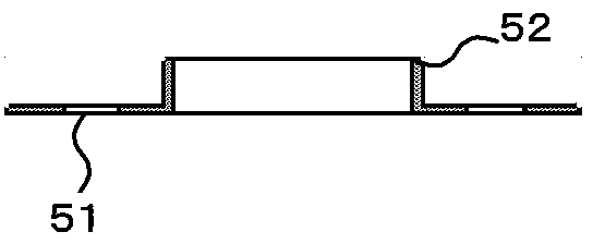
[0026] see figure 1 , represents the motor part arranged in the hermetic case 2 fixed in the rotary compressor RC and the compression mechanism P arranged under it. figure 2 yes figure 1 The X-X cross-section of , represents the partition plate 50 and the L layer viewed from the bottom of the casing 2 . Figure 3-Figure 4 is a detailed view of the partition plate 50 . Figure 5 It is a detailed diagram showing the compression mechanism P, the partition plate 50 , the relationship between the L layer and the R layer, and the oil supply circuit 18 to the slide plate 14 .

[0027] figure 1 The compression mechanism P includes a cylinder 11, a piston 13 that rotates eccentrically in the compression chamber 12 of the cylinder 11, a sliding plate 14 that reciprocates synchronously with the piston 13, an ecce...

Embodiment 2

[0053] In Example 1, refrigerant R290 and oil soluble in the refrigerant were used, but in Example 2, refrigerant R290, oil hardly soluble in the refrigerant, and insoluble oil that was hardly dissolved were used. In the description below, these are collectively referred to as non-dissolving oils. In addition, the specific gravity of these oils is close to that of Example 1.

[0054] R290 and non-dissolved oil form the L layer, and the condensed liquid refrigerant forms the R layer, and they form the separation layer. Therefore, the partition plate 50 having a specific gravity of 0.75 floats between these separation layers.

[0055] The oil that has finished lubricating the eccentric crankshaft 20, the main bearing and the auxiliary bearing, and the compression chamber 12 falls from the main bearing 30 to the upper end of the R layer, and due to the difference in specific gravity, the oil passes through the R layer from the upper end of the partition plate 50. The oil passag...


PUM


Abstract

The invention relates to a rotary compressor comprising a compressing mechanism and a motor arranged in a housing. An oil storage chamber is arranged on the bottom of the housing. Oil is stored in the oil storage chamber. A separation plate dividing the oil storage chamber into an upper part and a lower part is arranged in the oil storage chamber. The compressing mechanism is provided with an oil feeding mechanism. The oil feeding mechanism comprises an oil absorption pipe. An opening of the oil absorption pipe is between the separation plate and the bottom of the housing. A refrigerant and refrigerant oil with condensation proportion higher than that of the refrigerant are sealed in the housing. The compressing mechanism comprises a gas cylinder, a piston performing eccentric rotation in a compressing chamber of the gas cylinder, a slide sheet performing synchronous reciprocating rotation with the piston, an eccentric crank used for driving the piston, and a main bearing and an auxiliary bearing supporting the eccentric crank. The oil feeding mechanism is arranged on the lower end of the eccentric crank. The oil absorption pipe is inserted into a central hole of the eccentric crank. An oil absorption hole is arranged on the lower end of the oil absorption pipe. The compressor provided by the invention has the characteristics of simple and reasonable structure, flexible operation, good lubricating effect, wide application range, and the like.

Description

technical field [0001] The present invention relates to a rotary compressor. Background technique [0002] from reducing CO 2 From the perspective of emissions, refrigeration systems using hydrocarbon refrigerants are rapidly increasing globally. However, since the specific gravity of the condensed refrigerant or liquid refrigerant composed of hydrocarbons is about half of that of oil, the oil with less dissolved refrigerant is concentrated at the bottom of the shell, and the oil with more dissolved refrigerant is distributed above it. Therefore, this distribution relationship is contrary to conventional knowledge, and it is a problem that the compression mechanism that needs to be lubricated is soaked in low-viscosity oil. [0003] Due to the high flammability of hydrocarbon refrigerants such as R290, the amount of refrigerant and oil sealed in the refrigeration system will be limited. On the other hand, due to the very high solubility of hydrocarbon refrigerants to oil,...

Claims


Application Information

Patent Timeline
IPC IPC(8): F04C29/02
Inventor 小津政雄熊指挥
Owner GUANGDONG MEIZHI COMPRESSOR
Learn More