
Adjustable Laser Gas Telemeter and Its Focal Plane Adjustment Method

A laser gas, adjustable technology, applied in the direction of instruments, measuring devices, scientific instruments, etc., can solve the problem of being unable to meet the high-sensitivity measurement of long-distance and short-distance at the same time

Active Publication Date: 2015-09-23
HENAN HANWEI ELECTRONICS
View PDF11 Cites 0 Cited by
  • Summary
  • Abstract
  • Description
  • Claims
  • Application Information

AI Technical Summary

Problems solved by technology

[0004] The object of the present invention is to provide an adjustable laser gas telemeter and its focal plane adjustment method, so as to solve the problem of fixing the position of the detector in the existing laser gas telemeter, The technical problem of being unable to satisfy both long-distance and short-distance high-sensitivity measurements

Method used


Image

  • Adjustable Laser Gas Telemeter and Its Focal Plane Adjustment Method
  • Adjustable Laser Gas Telemeter and Its Focal Plane Adjustment Method
  • Adjustable Laser Gas Telemeter and Its Focal Plane Adjustment Method

Examples


Embodiment 1

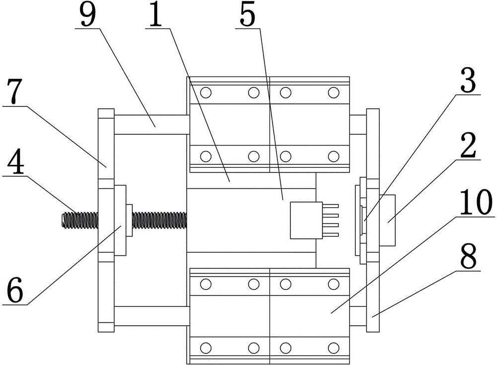
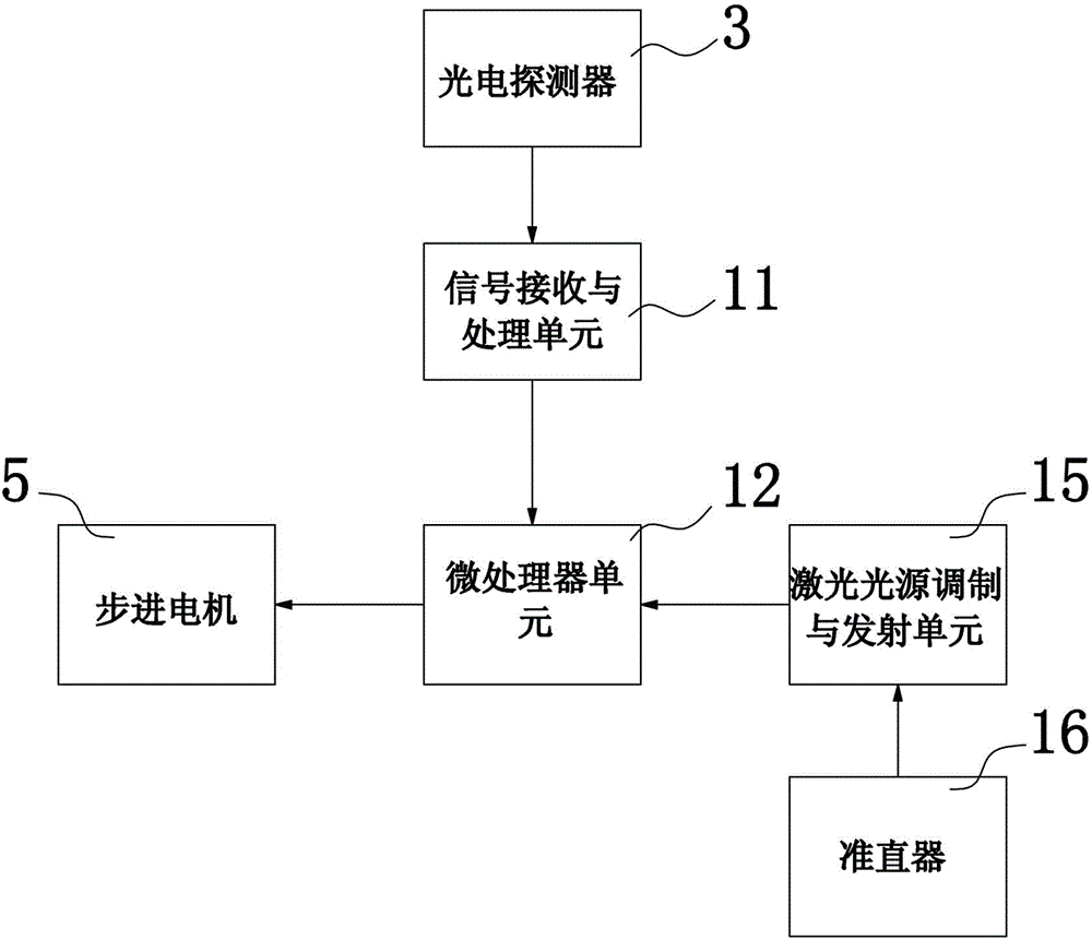
[0026] Such as figure 1 and figure 2 As shown, an adjustable laser gas telemetry instrument includes a microprocessor unit 12, a signal receiving and processing unit 11 electrically connected to the microprocessor unit 12, and a photodetector electrically connected to the signal receiving and processing unit 11 3. The optical filter 2 used in conjunction with the photodetector 3, the laser light source modulation and emission unit 15 electrically connected to the microprocessor unit 12, the collimator electrically connected to the laser light source modulation and emission unit 15 16. Condenser and focal plane adjustment mechanism. The condenser lens is generally a Fresnel lens, a concave mirror or a convex lens. The focal plane adjustment mechanism includes a base 1, a stepping motor 5 installed on the base 1, and a The leading screw 4 and the mounting frame on the output shaft of the stepping motor 5, the mounting frame is provided with a leading screw hole, the leading sc...

Embodiment 2

[0028]The difference between this embodiment and Embodiment 1 is that the mounting frame includes a guide rail, an adjustment plate arranged at one end of the guide rail, and a fixing plate arranged at the other end of the guide rail, and the screw hole is arranged on the adjustment plate. On the plate, the photodetector and the filter are installed on the fixed plate, and the base is provided with a guide rail guide hole, the guide rail is set in the guide rail guide hole, and the guide rail guide hole is arranged on the base On the other hand, it can also ensure the stable running of the fixed plate and the adjusting plate, saving the design of the slider.

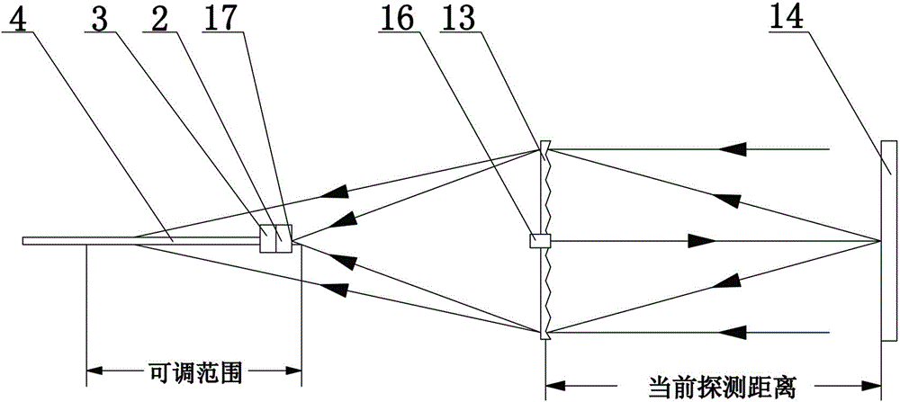
[0029] Such as image 3 As shown, a focal plane adjustment method of an adjustable laser gas telemeter, the focal plane adjustment method includes the following steps:

[0030] Step 1. Determine the calibration point at the current detection distance: start the adjustable laser gas telemeter, and the microprocessor unit...


PUM


Abstract

The invention provides a focal plane adjusting mechanism. The focal plane adjusting mechanism comprises a base, a stepping motor mounted on the base, a screw rod mounted on an output rotary shaft of the stepping motor and a mounting frame, wherein a screw rod screw hole is formed in the mounting frame; the screw rod is arranged in the screw rod screw hole; a photoelectric detector and a filter are mounted on the mounting frame; a microprocessor unit is electrically connected with a starting and stopping control unit of the stepping motor. The invention further provides a focal plane adjusting method of an adjustable laser gas remote sensing instrument. The adjustable laser gas remote sensing instrument provided by the invention has the advantages of scientific design, adjustable light-receiving surface, convenience for measurement in far and near distances, small volume and high performance cost ratio; the focal plane adjusting method of the adjustable laser gas remote sensing instrument has the advantages of scientific design, accuracy in positioning, high positioning speed and simplicity in operation.

Description

technical field [0001] The invention relates to a laser gas measuring device, in particular to an adjustable laser gas remote measuring instrument and a focal plane adjustment method thereof. Background technique [0002] The laser gas remote meter has a wide range of application requirements in natural gas stations and gas pipeline networks where gas leaks need to be detected. The common laser remote meter adopts the optical structure of transmitting and receiving. The laser light source of the remote meter emits a laser beam and irradiates the measurement target. After refraction or reflection, the telemeter receives the reflected light and gathers it on the photodetector, and analyzes the received light signal to obtain the gas information of the measurement target. The existing laser gas telemeter has roughly the structure Divided into transmissive and reflective types, mainly including background reflectors, filters, condensers, photodetectors and control processing sys...

Claims


Application Information

Patent Timeline
Patent Type & Authority Patents(China)
IPC IPC(8): G01N21/01
Inventor 王书潜郭东歌张小水李志刚陈海永贾林涛
Owner HENAN HANWEI ELECTRONICS
Learn More