
Method for identifying state of power transformer winding by using pseudorandom sequence

A pseudo-random sequence and power transformer technology, applied in the high-voltage field, can solve the problems of misjudgment and misjudgment, insensitive analysis technology, long measurement time of FRA method, etc., and achieve the effect of short measurement time and easy and accurate judgment

Active Publication Date: 2013-11-20
XI AN JIAOTONG UNIV
View PDF6 Cites 7 Cited by
  • Summary
  • Abstract
  • Description
  • Claims
  • Application Information

AI Technical Summary

Problems solved by technology

[0003] However, there are still problems in the use of the frequency response method (FRA method): 1) When the signal source of the FRA test system outputs a single frequency, it generally outputs multiple cycles continuously, and uses the middle part of the excitation and response signals to analyze; then in the next frequency On-point test analysis; this leads to a long measurement time of the FRA method, which is not conducive to the rapid processing of data
Take up a lot of storage space
Moreover, for graphic data with small local differences, the same feature value and judgment can be obtained. If the small local differences reflect the winding status and trend, it may cause misjudgment and misjudgment. That is to say, analysis based on graphics technology less sensitive

Method used


Image

  • Method for identifying state of power transformer winding by using pseudorandom sequence
  • Method for identifying state of power transformer winding by using pseudorandom sequence
  • Method for identifying state of power transformer winding by using pseudorandom sequence

Examples


Embodiment Construction

[0024] The present invention will be described in further detail below in conjunction with the accompanying drawings.

[0025] see figure 1 , the present invention comprises the following steps:

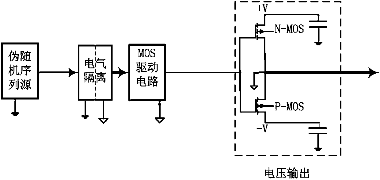
[0026] 1) The winding of the transformer is regarded as a kind of object to be identified. By using the method in the system identification theory, the M sequence in the pseudo-random sequence is used as the signal source (such as figure 2 shown), where the clock frequency of the M sequence is 500kHz to 6MHz, and the series is 7th to 13th order; after the winding system is excited, the input and output signals are collected by a dual-channel digital acquisition device;

[0027] 2) Calculate the impulse response transfer function of the system according to the input and output signals.

[0028] The specific process is as follows:

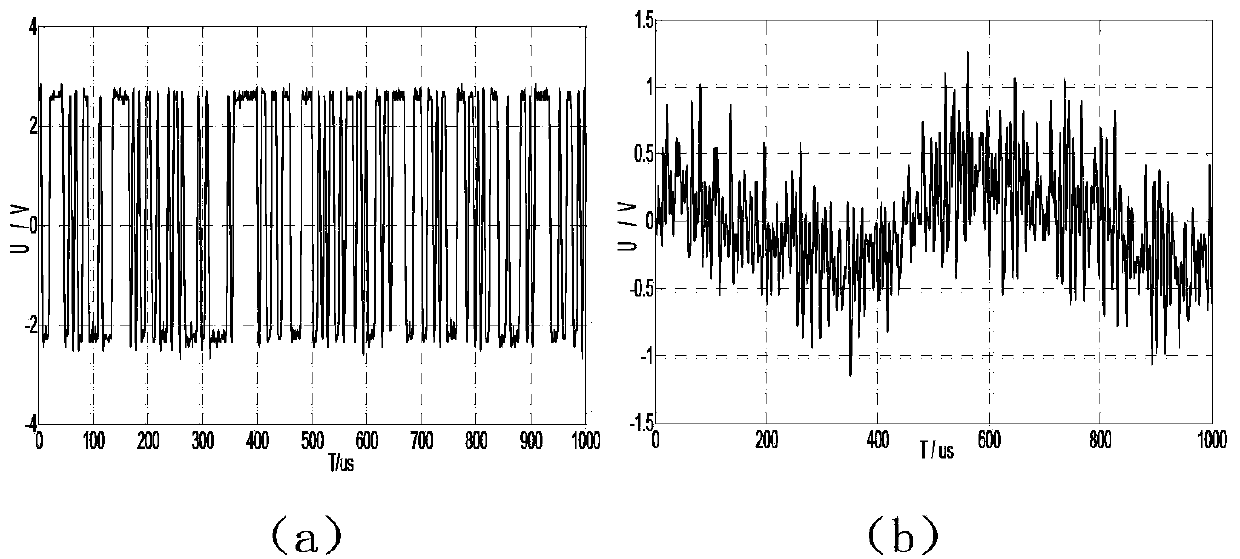
[0029] At the input end of the winding system, input the M sequence signal x(k) generated by the pseudo-random sequence generator (such as image 3 (a...


PUM


Abstract

The invention provides a method for identifying a state of a power transformer winding by using a pseudorandom sequence. The method comprises the following steps: adopting an M sequence in the pseudorandom sequence as a signal source; after exciting a winding system, collecting input and output signals by using double-channel digital collection equipment; calculating to obtain a pulse response transferring function of the winding system according to the input and output signals; then carrying out correlation function calculation on the input and output signals to obtain a pulse response of the winding system; then describing the state of the winding according to a derivation parameter and a frequency response curve; and judging whether the transformer winding is deformed or not. The testing method disclosed by the invention can be used for comparing amplitude-frequency response curves of the transformer winding and has the consistency. The method disclosed by the invention has the characteristics that the pulse response transferring function of the winding can be directly obtained, the measurement time is short and the like; and furthermore, the method disclosed by the invention can judge the state of the transformer winding according to the change of specific parameters, including poles, null points and the like, of the transferring function, so that the problem in the prior art that technicists easily carry out erroneous judgment is solved.

Description

technical field [0001] The invention belongs to the technical field of high voltage, and in particular relates to a method for identifying the winding state of a power transformer by using a pseudo-random sequence. Background technique [0002] With the continuous growth of the power grid, the short-circuit current and short-circuit capacity in the system increase, and the short-circuit faults of power transformers, reactors and other equipment in operation often occur, and their windings will also be more likely to encounter Deformation and other faults, the state of the winding, that is, whether the winding is deformed under the normal state, is a basic sign of the operating state of the transformer. The existing detection methods for transformer windings include short-circuit impedance method, low-voltage pulse method, frequency response method, etc. Among them, the short-circuit impedance method is relatively simple to operate, and there are molding equipment for field u...

Claims


Application Information

Patent Timeline
Patent Type & Authority Applications(China)
IPC IPC(8): G01R31/06
Inventor 罗勇芬王明松陈鹏李彦明沈煜
Owner XI AN JIAOTONG UNIV
Learn More