Method for shaping round beam into spot beam and annular beam

A ring beam and beam shaping technology, which is applied in the field of non-imaging optics, can solve the problems of large terminal volume, complex structure of terminal optical system, unfavorable development of terminal miniaturization, etc., and achieve the effect of reducing terminal volume and improving tracking stability

Inactive Publication Date: 2013-11-20
HARBIN INST OF TECH
View PDF4 Cites 2 Cited by
  • Summary
  • Abstract
  • Description
  • Claims
  • Application Information

AI Technical Summary

Problems solved by technology

Depend on figure 2 It can be seen that there are two optical paths (tracking part and communication part) in the receiving system, resulting in too complex structure of the terminal optical system, increasing the complexity of system installation and adjustment, and the terminal volume is too large, which is not conducive to the development of the terminal in the direction of miniaturization

Method used


Image

  • Method for shaping round beam into spot beam and annular beam
  • Method for shaping round beam into spot beam and annular beam
  • Method for shaping round beam into spot beam and annular beam

Examples


specific Embodiment approach 1

[0038] Specific implementation mode one: combine Figure 1 to Figure 7 Describe this embodiment mode, a kind of method that is used to realize circular light beam shaping into point ring beam in this embodiment mode is realized according to the following steps:

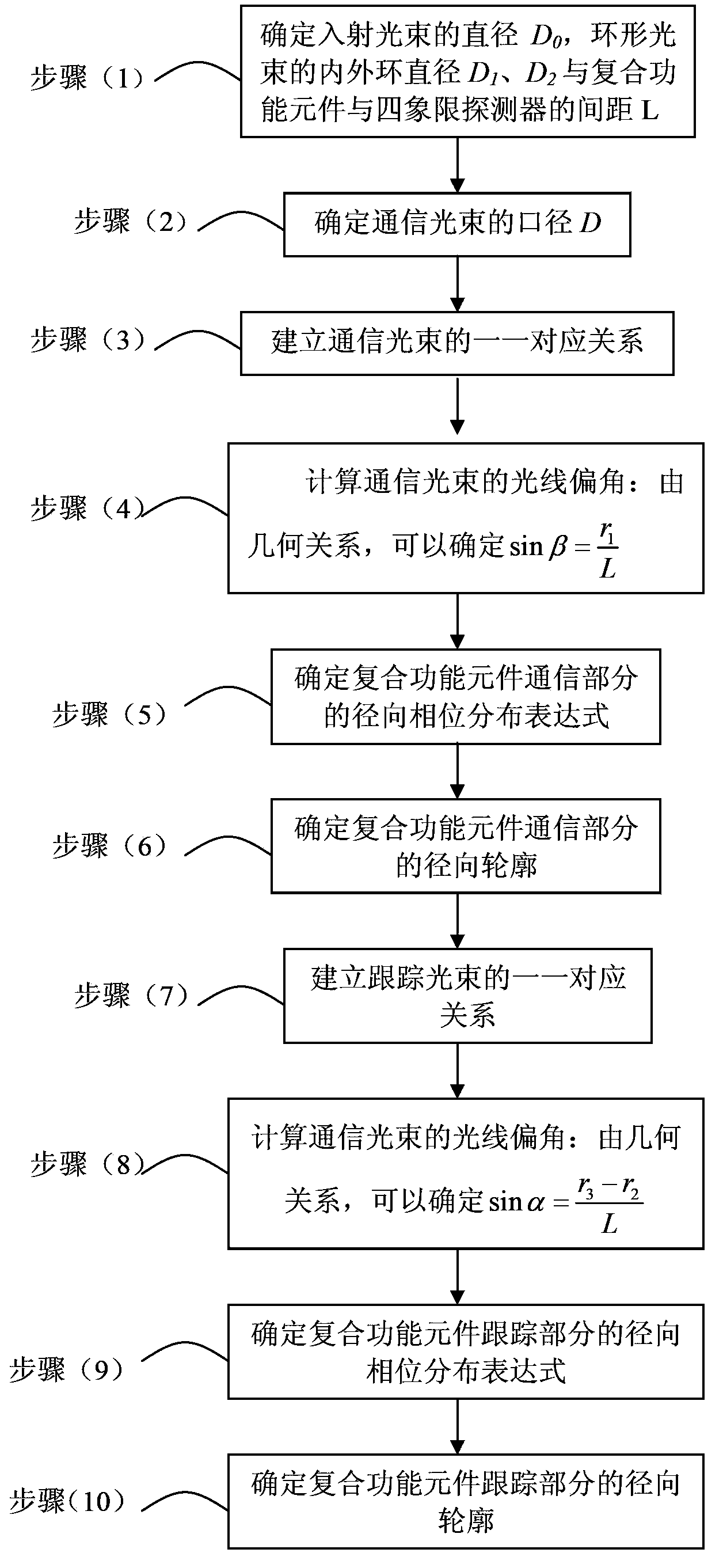
[0039] The specific steps of the design method for shaping a circular beam into a ring beam are as follows:

[0040] (1) if Figure 5 , to determine the diameter D of the incident beam 0 , the diameter of the inner and outer rings of the ring beam D 1 、D 2 , and the distance L between the composite functional element and the four-quadrant detector: If the aperture of the optical antenna is d and its magnification is T, then D 0 =d / T;

[0041] (2) if Figure 5 , to determine the aperture D of the communication beam: if the communication optical power accounts for η of the incident optical power, then

[0042] D = η D 0

[004...

specific Embodiment approach 2

[0066] Specific implementation mode two: the difference between this implementation mode and specific implementation mode one is: the D described in step (1) 1 and D 2 It is mainly related to the size of the four-quadrant detector, and it should be ensured that they are all within the detection range of the detector; take L≥2D 0 . Other steps and parameters are the same as those in Embodiment 1.

specific Embodiment approach 3

[0067] Embodiment 3: This embodiment differs from Embodiment 1 or Embodiment 2 in that: in step (2), 0<η<1, which is determined by parameters such as incident light power and bit error rate. Other steps and parameters are the same as those in Embodiment 1 or Embodiment 2.


PUM


Abstract

The invention relates to the field of non-image optics, provides a method for shaping a round beam into a spot beam and an annular beam, and aims to lower the complexity of the installing and debugging of the receiving system of an inter-satellite optical communication terminal and simplify the optical system structure of the inter-satellite optical communication terminal. The method comprises the following steps: (1) determining the diameter D0 of an incident beam; (2) determining the calibre D of a communication beam; (3) building a one to one correspondence relationship for the communication beam; (4) calculating the ray declination angle of the communication beam; (5) determining the radial phase distribution expression of the communication part of a complex function element; (6) determining the radial outline of the communication part of the complex function element; (7) building a one to one correspondence relationship for a tracking beam; (8) calculating the ray declination angle of the tracking beam; (9) determining the radial phase distribution expression of the tracking part of the complex function element; (10) determining the radial outline of the tracking part of the complex function element. The method is applicable to the field of non-imaging optics.

Description

technical field [0001] The invention relates to the field of non-imaging optics, in particular to a method for shaping a circular light beam into a spot ring light beam. Background technique [0002] The receiving system of the satellite optical communication terminal mainly includes a tracking detection system and a communication system. A typical satellite optical communication terminal optical system mainly consists of an optical antenna (1), a beam splitter (2), a communication focusing lens group (3), a communication detector (4), a tracking focusing lens group (5) and a tracking detector (6 ) composition, such as figure 2 shown. When the terminal receives an optical signal, the incident light beam is narrowed by the afocal optical antenna (1), and the incident light is divided into a tracking optical path and a communication optical path. The former part of the light is reflected by the beam splitter (2) and focused on the tracking detector (6) through the tracking ...

Claims


Application Information

Patent Timeline
Patent Type & Authority Applications(China)
IPC IPC(8): G02B27/09H04B10/118
Inventor 胥全春俞建杰刘永凯周彦平于思源杜继东谢小龙高鹏涛马晶谭立英
Owner HARBIN INST OF TECH
Why Eureka
Try Eureka