Capacitive silicon microphone provided with vibrating membrane with concave-convex structure, and preparation method thereof

A technology of silicon microphone and capacitive type, which is applied in the field of capacitive silicon microphone and its preparation, can solve the problems of internal stress difference of silicon microphone chip vibrating film, affect device performance process consistency, and small mechanical vibration range, etc., to improve internal stress The non-uniformity problem, the effect of improving the mechanical tolerance and improving the mechanical performance

Inactive Publication Date: 2013-11-20
SHANGHAI INTEGRATED CIRCUIT RES & DEV CENT
View PDF6 Cites 12 Cited by
  • Summary
  • Abstract
  • Description
  • Claims
  • Application Information

AI Technical Summary

Problems solved by technology

[0005] In actual production, polysilicon thin films are usually formed by low-pressure chemical vapor deposition (LPCVD) as the diaphragm of silicon microphones. There will be differences in internal stress gradients between different regions of this film, and the diaphragms of silicon microphone chips in each production batch The internal stress will also have obvious differences, which will affect the consistency of device performance and process; at the same time, the traditional diaphragm structure is a flat planar structure. Under the action of a certain sound pressure, its mechanical vibration range is small and its sensitivity is low.

Method used


Image

  • Capacitive silicon microphone provided with vibrating membrane with concave-convex structure, and preparation method thereof
  • Capacitive silicon microphone provided with vibrating membrane with concave-convex structure, and preparation method thereof
  • Capacitive silicon microphone provided with vibrating membrane with concave-convex structure, and preparation method thereof

Examples


Embodiment Construction

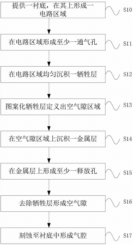
[0022] The specific embodiment of the present invention will be further described in detail below in conjunction with the accompanying drawings.

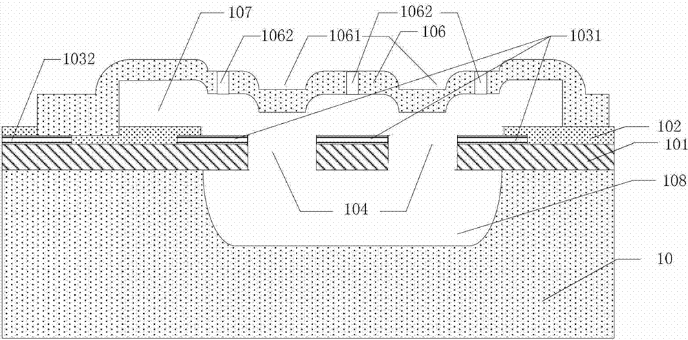
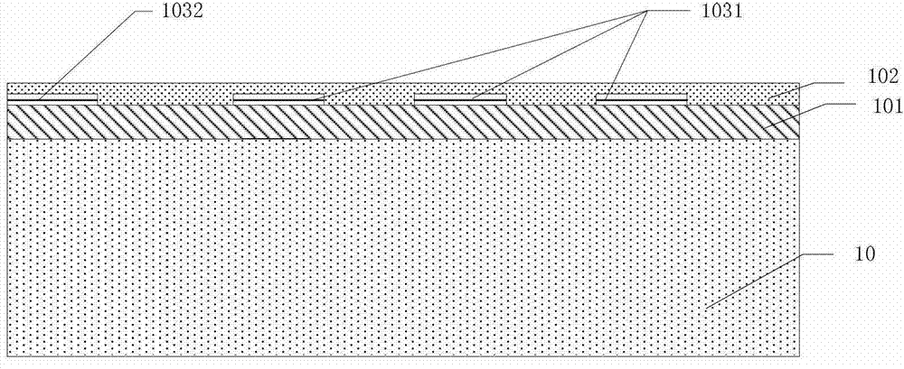
[0023] Such as figure 1 As shown, the first embodiment of the present invention provides a capacitive silicon microphone, formed on a flat circuit region 10 of the substrate, including: a passivation layer 102, which is the surface layer of the circuit region 10; a dielectric layer 101, arranged between the passivation layer 102 and the substrate; a device group, embedded in the bottom of the passivation layer 102, which includes a first device 1031 and a second device 1032, the first device 1031 is a capacitive second device of a capacitive silicon microphone One pole; An air gap 107, located above the passivation layer 102, is used as the insulating medium of the capacitive silicon microphone; An air cavity 108 is formed in the substrate; The circuit area penetrates the passivation layer 102 and the dielectric layer 101 downwards...


PUM


Abstract

The invention relates to a capacitive silicon microphone which is formed on a circuit area on a semiconductor substrate, and comprises a passivation layer, a dielectric layer, a device group, an air gap, an air cavity, at least one vent hole and a metal layer, wherein the passivation layer is a surface layer of the circuit area; the dielectric layer is arranged between the passivation layer and the substrate; the device group is embedded at the bottom of the passivation layer and comprises a first device and a second device; the air gap is arranged above the passivation layer; the air cavity is formed in the substrate; the at least one vent hole passes through the passivation layer and the dielectric layer downwards from the circuit area where the device group is not laid, and is respectively communicated with the air cavity and the air gap; the metal layer comprises a first part and a second part which are connected with each other, wherein the first part covers the air gap, and the second part passes through the passivation layer and is connected with the second device; the upper surface of the first part comprises at least one release hole and at least one concave part, wherein the position of each concave part corresponds to that of each vent hole. The capacitive silicon microphone can effectively improve the uniformity of the stress in a vibrating membrane of the silicon microphone, and can improve the sensitivity of the silicon microphone.

Description

technical field [0001] The invention relates to the field of semiconductor processing and manufacturing, and more specifically relates to a capacitive silicon microphone with a concave-convex structure diaphragm and a preparation method thereof. Background technique [0002] The working principle of the electret microphone is that the human voice causes the electret diaphragm to vibrate through the air to cause displacement, so that the distance between the back electrode and the metal layer on the electret changes, and the capacitance also changes accordingly. Change, since the number of charges on the electret remains constant, it can be concluded from Q=CU that when C changes, the voltage U across the capacitor will change, thereby outputting an electrical signal and realizing the conversion from an acoustic signal to an electrical signal. [0003] The key element of acoustic-electric conversion is the electret diaphragm. However, the traditional electret condenser micro...

Claims


Application Information

Patent Timeline
Patent Type & Authority Applications(China)
IPC IPC(8): H04R19/04H04R31/00
Inventor 左青云康晓旭袁超
Owner SHANGHAI INTEGRATED CIRCUIT RES & DEV CENT
Why Eureka
Try Eureka