
Electromagnetic deflection scanning coil for machining electron beam

A technology of electron beam processing and electromagnetic deflection, applied in electron beam welding equipment, metal processing equipment, manufacturing tools, etc., can solve the problems of bulkiness, large coil size design, increase manufacturing cost, etc., and improve the deflection scanning frequency. , reduced size and weight, improved uniformity

Inactive Publication Date: 2013-11-27
NANJING UNIV OF SCI & TECH
View PDF5 Cites 9 Cited by
  • Summary
  • Abstract
  • Description
  • Claims
  • Application Information

AI Technical Summary

Problems solved by technology

In the structural design of the deflection coil, the traditional structural design is relatively simple. There are bipolar shoe structures and ring structures without magnetic rings: among them, the bipolar shoe structure requires high perpendicularity in two directions, and the precision of machining, The positioning of the pole pieces and the precision of the winding will directly affect the uniformity of the magnetic field; and in order to obtain a larger width of the magnetic field, the outer dimensions of the coil need to be designed to be large, which is cumbersome and increases the manufacturing cost; The direction of the magnetic field on the outer side and the center of the coil is just opposite, and some magnetic field strengths will cancel each other out, limiting the size of the generated magnetic field to a greater limit

Method used


Image

  • Electromagnetic deflection scanning coil for machining electron beam
  • Electromagnetic deflection scanning coil for machining electron beam
  • Electromagnetic deflection scanning coil for machining electron beam

Examples


Embodiment 1

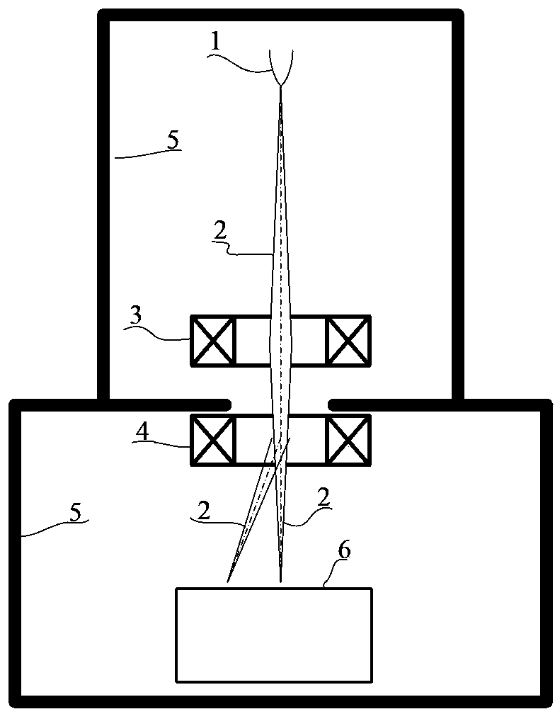
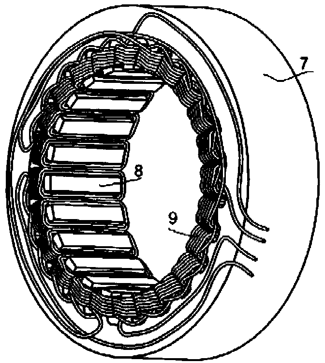
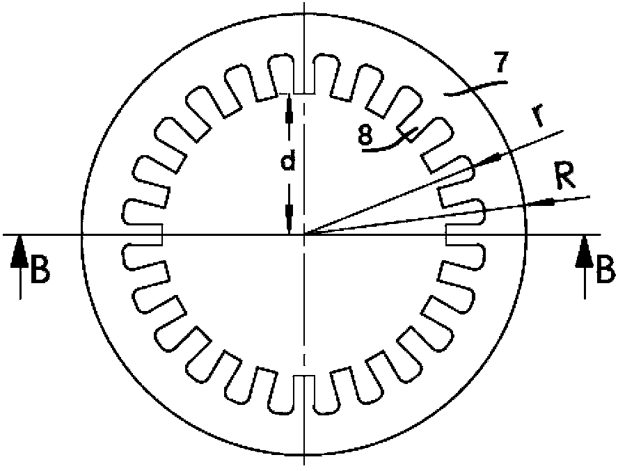
[0021] combine Figure 3~5 , designed an electromagnetic deflection scanning coil for electron beam processing, the specific structural parameters are: see image 3 , the number of magnetic poles 8 is 4N=24 (N=6), the outer diameter R of the magnetic ring 7 of the magnetic core frame is 110mm, the inner diameter r of the magnetic ring 7 is 90mm, and the distance between each magnetic pole surface and the outer center of the magnetic ring 7 The distance d is 35mm, combined with Figure 4 , the height h of the magnetic core skeleton is 30mm, and the entire magnetic core skeleton is pressed and formed by iron-based amorphous material.

[0022] Electron beam processing equipment chooses electron beam welding machine of model ZD150-15A, which is provided by Beijing Aeronautical Manufacturing Engineering Research Institute. The maximum accelerating voltage of the welding machine is 150kV, and the maximum beam current intensity is 100mA. For the workpiece welding working distance c...


PUM

PropertyMeasurementUnit
heightaaaaaaaaaa

Abstract

The invention discloses an electromagnetic deflection scanning coil for machining an electron beam. The electromagnetic deflection scanning coil comprises a magnetic core framework and coil windings (9). The magnetic core framework comprises a magnetic ring (7) and magnetic poles (8) which are formed integrally. The coil windings (9) are wound on all the magnetic poles (8) of the magnetic core framework, the number of the magnetic poles (8) is 4N, N is the integer larger than or equal to 3, and the magnetic poles (8) of the magnetic core framework are made of a soft magnetic material. By means of the electromagnetic deflection scanning coil of the structure, the evenness of an electron beam deflection scanning magnetic field is improved, the size and the weight of coils are reduced, and manufacture cost is saved. In addition, by means of the soft magnetic material, deflection scanning frequency of the electron beam is improved, and eddy-current loss is reduced.

Description

technical field [0001] The invention belongs to the technical field of electron beam processing, in particular to an electromagnetic deflection scanning coil for electron beam processing. Background technique [0002] For an electron beam processing equipment, in order to study the difference between the theoretical design of the electron gun and the actual situation, the influence of factors such as the stability of the electron gun power supply system and the change of vacuum degree on the electron beam current, it is necessary to accurately study the characteristics of the beam current and measure the electron beam. The distribution of the beam current power density, but due to the high power of the electron beam used for welding and the high power density of the focus, it can melt any refractory material, which brings difficulties to the measurement. [0003] The high-speed deflection scanning of the electron beam can disperse the energy to the entire scanning area, avoi...

Claims


Application Information

Patent Timeline
Patent Type & Authority Applications(China)
IPC IPC(8): B23K15/00
Inventor 彭勇王晓宇周绮王克鸿左从进许海鹰石美玲张海宁钱红丽杨立
Owner NANJING UNIV OF SCI & TECH
Learn More