Turbulent micro burner preheated by exhaust gas

A micro-burner and waste gas technology, which is applied to gas fuel burners, burners, combustion methods, etc., can solve the problems of limited combustion efficiency, poor organization of fuel-oxidant mixture gas flow, poor combustion stability, etc. Small radiant heat loss, improved overall performance, effect of stabilizing the flame

Inactive Publication Date: 2013-11-27
JIANGSU UNIV
View PDF4 Cites 6 Cited by
  • Summary
  • Abstract
  • Description
  • Claims
  • Application Information

AI Technical Summary

Problems solved by technology

This type of combustion chamber has a rectangular parallelepiped structure, with one side for intake and one side for exhaust. The air

Method used


Image

  • Turbulent micro burner preheated by exhaust gas
  • Turbulent micro burner preheated by exhaust gas
  • Turbulent micro burner preheated by exhaust gas

Examples


Embodiment Construction

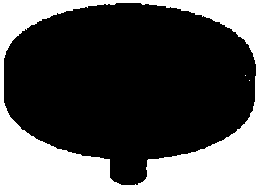
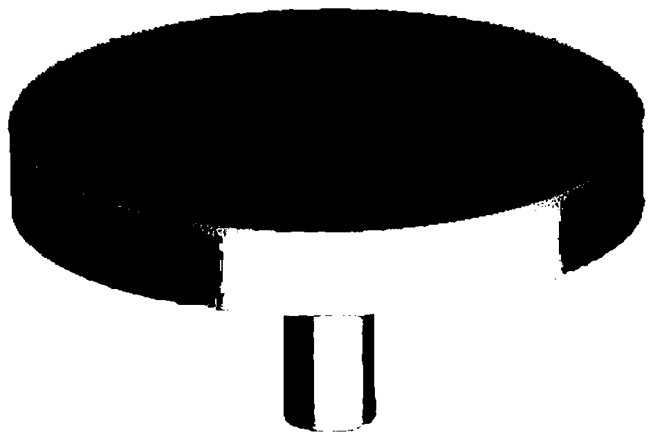
[0027] Below in conjunction with accompanying drawing and embodiment the present invention will be further described, see Figure 5, the present invention has a flat cylindrical combustion chamber, premixed gas enters from the intake pipe, and is preheated by exhaust gas flowing through the exhaust pipe and exhaust chamber during the intake process, and the preheated gas enters from three inlets respectively In the combustion chamber, the gas forms a swirling flow in the combustion chamber to realize vortex combustion. The high temperature of the combustion radiates through the wall surface and radiates from the surface of the combustion chamber.

[0028] see Figure 6 and Figure 7 , wherein, 1-combustion chamber; 2-intake chamber; 3-exhaust chamber; 4-intake pipe; 5-exhaust pipe; 6-combustion chamber inlet; 9-combustion chamber wall lamination; 10-heat shield; 11-inlet chamber casing; 12-exhaust chamber casing; 13-auxiliary line, the auxiliary line is on the plane where th...


PUM


Abstract

The invention relates to a turbulent micro burner preheated by exhaust gas. The turbulent micro burner comprises a combustion chamber, a gas inlet chamber, an exhaust chamber, a gas inlet pipe and an exhaust pipe, wherein the combustion chamber, the gas inlet chamber and the exhaust chamber are all flat cylinders; the gas inlet pipe and the exhaust pipe are cylinders; the combustion chamber is arranged in the gas inlet chamber; the top of the combustion chamber is communicated with the inner surface of the top of the gas inlet chamber; the combustion chamber is provided with three combustion chamber inlets which are formed in the side surfaces of the combustion chamber respectively; every two adjacent combustion chamber inlets are spaced at an interval of one third of an arc; an included angle formed between an axis of each combustion chamber inlet and a round edge tangent line of the combustion chamber is 30 degrees; a combustion chamber exhaust port is formed in the center of a top section of the combustion chamber and is round, and a circle center of the combustion chamber exhaust port is located in an axis of the combustion chamber; the gas inlet pipe is arranged in a center of the lower surface of the gas inlet chamber, and a section area is equal to that of the combustion chamber exhaust port; the gas inlet chamber is arranged in the exhaust chamber; the gas inlet chamber and the exhaust chamber are connected through fixing supporting columns; the exhaust pipe is arranged in the center of the lower surface of the exhaust chamber, and the section area is larger than that of the gas inlet pipe; and a layer of a heat insulation material is arranged on the outer layer of the exhaust chamber and the outer layer of the exhaust pipe.

Description

technical field [0001] The invention belongs to the technical field of micro-power electromechanical systems, specifically relates to a micro-thermal photoelectric device, and is an innovative design of a combustion chamber structure based on a micro-scale premixed combustion technology and a vortex combustion technology. Change the flat-plate combustion chamber into a flat cylindrical combustion chamber, redesign the overall structure, arrange the inlet and outlet, use the exhaust gas after combustion to preheat the gas, and the preheated gas will form a vortex after entering the combustion chamber, thereby realizing vortex combustion. Improve the overall performance of micro-thermophotovoltaic systems. Background technique [0002] The micro-power electromechanical system converts the chemical energy of hydrogen or hydrocarbon fuel into heat energy directly through combustion in the micro-system, and then relies on a variety of energy conversion methods to provide power or...

Claims


Application Information

Patent Timeline
IPC IPC(8): F23D14/02F23D14/66F23D14/46
CPCY02E20/34
Inventor 潘剑锋陈瑞唐爱坤范宝伟胡松
Owner JIANGSU UNIV
Why Eureka
Try Eureka