Method capable of accurately measuring phase delay quantity of wave plate

A wave plate phase and precise measurement technology, applied in the direction of testing optical performance, etc., can solve the problems of difficulty in accurately extracting peak wavelength, affecting measurement results, adjustment errors, etc.

Inactive Publication Date: 2013-11-27
SHANDONG JIAOTONG UNIV
View PDF5 Cites 15 Cited by
  • Summary
  • Abstract
  • Description
  • Claims
  • Application Information

AI Technical Summary

Problems solved by technology

The patent number is ZL200510030094.8, and the title of the invention is "Method and Device for Measuring the Thickness of a Birefringent Uniaxial Crystal Wave Plate", which discloses a method for measuring the thickness of a birefringent uniaxial crystal wave plate. The peak wavelength is used to calculate the thickness of the wave plate, but in the actual measurement process, since the rate of change of the curve near the peak wavelength tends to zero, and sometimes there are multiple peaks, it is very difficult to accurately extract the peak wavelength, and the extracted peak wavelength will be There are considerable errors, which will eventually bring large errors to the measurement results; at the same time, this method requires that the polarizer and the polarizer should be parallel or perpendicular to each other during the measurement process, and the fast axis of the wave plate to be measured should be in line with the polarizer. The included angle of the light transmission axis of the sensor is π / 4 or 3π / 4, and there will be adjustment errors in the actual measurement process, which will also affect the final measurement results
The measurement methods proposed by most other literatures can only measure the effective phase delay of the wave plate and cannot measure the absolute phase delay (see literature: [1] Hou Junfeng, Yu Jia, Wang Dongguang, Deng Yuanyong, Zhang Zhiyong, Sun Yingzi, "Self-calibration method Measuring Waveplate Phase Retardation", [China Laser] Vol.39, No.4.2012, pp173)

Method used


Image

  • Method capable of accurately measuring phase delay quantity of wave plate
  • Method capable of accurately measuring phase delay quantity of wave plate
  • Method capable of accurately measuring phase delay quantity of wave plate

Examples


Embodiment 1

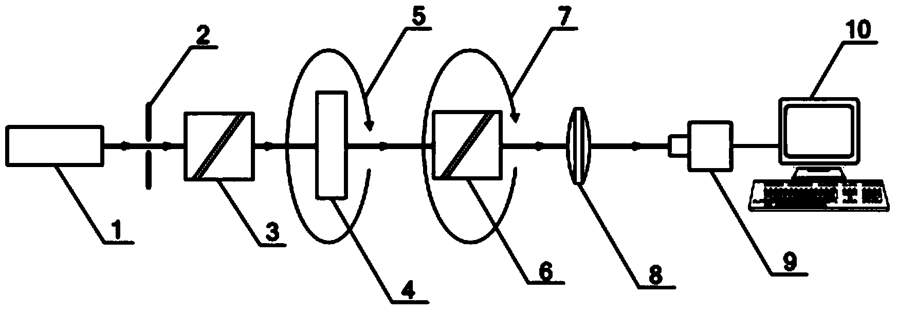
[0082] Embodiment 1 of the present invention such as figure 1 , 2 , 3, a method for accurately measuring the phase retardation of a wave plate is realized by the following device, which includes a light source 1, an aperture 2, a polarizer 3, an analyzer 6, a converging lens 8, a spectrometer 9 and The computer 10, the light source 1 is located in front of the diaphragm 2, and the polarizer 3, the analyzer 6, the converging lens 8 and the spectrometer 9 are placed sequentially along the optical path from the diaphragm 2, and the spectrometer 9 is connected to the computer 10, wherein the polarizer is located Place the first polarizer frame 5 between the detector 3 and the analyzer 6, the first polarizer frame 5 is used to install the wave plate 4 to be measured, and the analyzer 6 is installed on the second polarizer frame 7, the method steps are as follows :

[0083] (1) Turn on the light source and let the light source warm up for more than 15 minutes until the output wave...

Embodiment 2

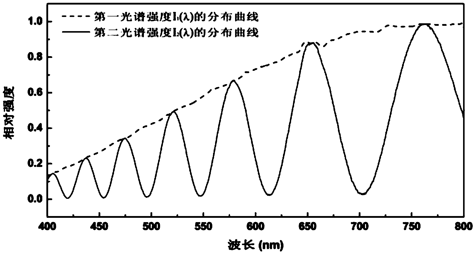
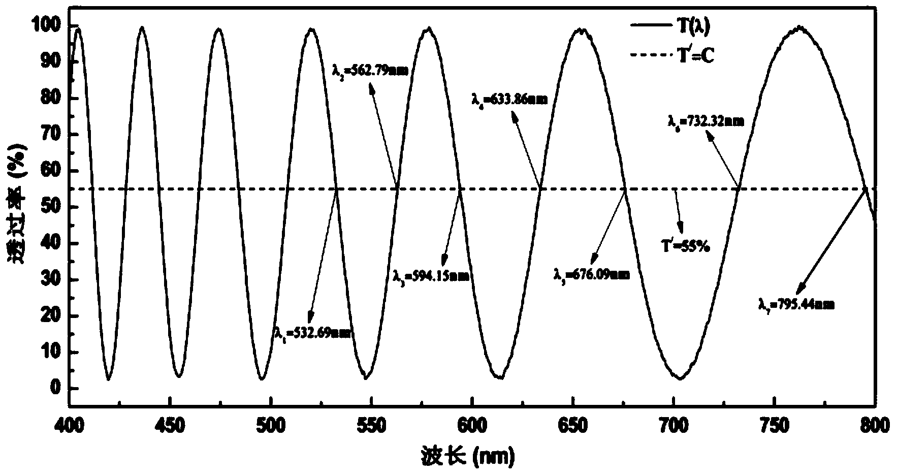
[0096] Same as Example 1, except that step (5) of this method is: keep the orientation of the polarizer and the analyzer unchanged, install the wave plate to be tested on the first polarizer frame and place it between the polarizer and the analyzer Between the polarizers, rotate the first polarizer frame to adjust the fast axis direction of the wave plate to be tested, find the maximum light intensity by visual inspection of the light intensity of the light emitted from the polarizer, and then rotate the first polarizer clockwise from this position Rotate the wave plate to be measured to 60°, and measure the second spectral intensity curve I obtained from the light emitted from the analyzer according to the measurement procedure in step (4). 2 (λ) and store the corresponding measured data in the computer.

Embodiment 3

[0098] Same as Example 1, except that step (5) of this method is: keep the orientation of the polarizer and the analyzer unchanged, install the wave plate to be tested on the first polarizer frame and place it between the polarizer and the analyzer Between the polarizers, rotate the first polarizer frame to adjust the fast axis direction of the wave plate to be tested, find the maximum light intensity by visual inspection of the light intensity of the light emitted from the polarizer, and then rotate the first polarizer clockwise from this position Rotate the wave plate to be measured to 30°, and measure the second spectral intensity curve I obtained from the light emitted by the analyzer according to the measurement procedure in step (4). 2 (λ) and store the corresponding measured data in the computer.


PUM


Abstract

A method capable of accurately measuring the phase delay quantity of a wave plate belongs to the technical field of parameter measurement of the wave plate. A device comprises a light source, a diaphragm, a polarizer, the wave plate to be detected, a polarization analyzer, a spectrometer and a computer. A uniformization spectrum transmittance T (lambda) curve can be obtained by measuring a first spectrum intensity I1 (lambda) distribution curve and a second spectrum intensity I2 (lambda) distribution curve. The computer is utilized to calculate the phase delay quantity and other a plurality of physical parameters of the wave plate to be detected according to the wave length of the intersection point between a line with the transmittance as a fixed value and the uniformization spectrum transmittance T (lambda) curve. The method is a non-contact nondestructive measurement technique and can acquire the plurality of physical parameters of the absolute phase delay quantity, the effective phase delay quantity, the thickness, the level and the like of the wave plate to be detected in a wide spectrum range. The method is high in measuring accuracy, a measuring device is easy to adjust, requirements for the position of the polarizer, the position of the wave plate to be detect and the position of the polarization analyzer are not strict, and the method is suitable for measuring a non-compound crystalline wave plate.

Description

technical field [0001] The invention relates to wave plate measurement, in particular to a method for accurately measuring wave plate phase delay. Background technique [0002] The wave plate is an important polarizing device, which is widely used in the fields of modern optical precision measurement technology and polarization technology. The phase delay of the wave plate is the most important technical parameter of the wave plate, and its own accuracy will directly affect the measurement accuracy of the entire system. The phase delay of the wave plate is the additional phase difference between two optical vibrations whose vibration directions are perpendicular to each other. According to the size of the additional phase difference generated by the wave plate, the wave plate can be divided into two categories: one is the phase delay δ 0 A wave plate less than 2π is called a zero-order wave plate. The thickness of the zero-order wave plate is too thin, difficult to process...

Claims


Application Information

Patent Timeline
Patent Type & Authority Applications(China)
IPC IPC(8): G01M11/02
Inventor 王伟梁志强陈建中
Owner SHANDONG JIAOTONG UNIV
Why Eureka
Try Eureka