Non-radioactivity ionization source and application thereof

An ionization source, radioactive technology, applied in ion source/gun, parts of particle separator tubes, material analysis by electromagnetic means, etc., can solve the problems of low photoelectron concentration, small light-receiving area, unstable physical and chemical properties, etc. , to achieve the effect of high photoelectron concentration

Inactive Publication Date: 2013-11-27
BEIJING TELESOUND ELECTRONICS
View PDF5 Cites 9 Cited by
  • Summary
  • Abstract
  • Description
  • Claims
  • Application Information

AI Technical Summary

Problems solved by technology

However, the light-receiving area of ​​metal grid or metal ring is small, the concentration of photoelectrons generated is low, and the physical and chemical properties are unstable under normal temperature and pressure.

Method used


Image

  • Non-radioactivity ionization source and application thereof
  • Non-radioactivity ionization source and application thereof
  • Non-radioactivity ionization source and application thereof

Examples


Embodiment 1

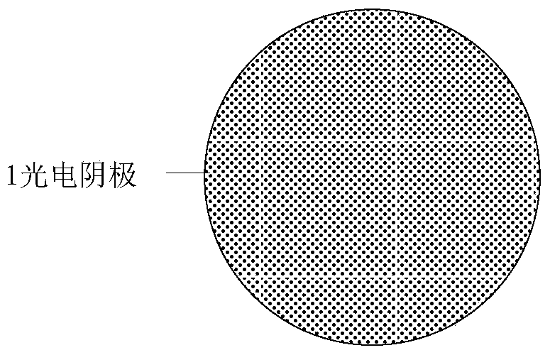
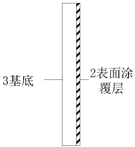
[0030] The preparation method of the ultraviolet photocathode: the photocathode 1 is circular, with a diameter of 23 mm, including a substrate 3 and a surface coating layer 2 (see figure 1 with figure 2 ). The substrate is made of fused silica with high UV transmittance, with a thickness of 1.5mm. The surface coating layer is made of high-purity Au, and the thickness of the gold film is 120nm. The coating method is vacuum evaporation metal thin film method.

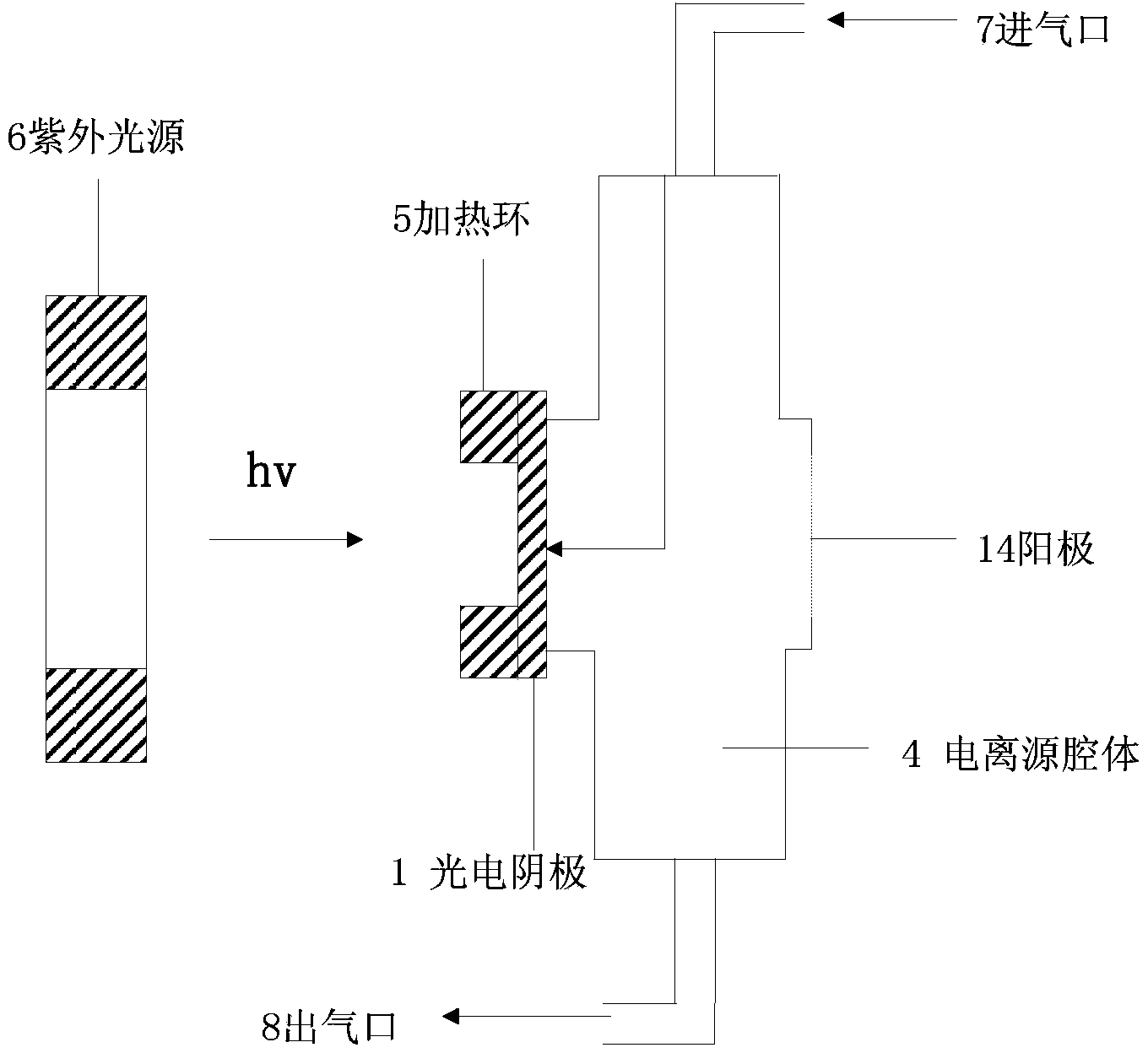
[0031] See image 3 , is a structural schematic diagram of the ionization source of the present invention. The ionization source using the photoelectric effect includes an ultraviolet light source 6, a photocathode 1, a heating ring 5 (heating temperature control device), and its temperature control parameter is 140-180 ° C; and an ionization source cavity 4, and the side wall of the ionization source cavity 4 An air inlet 7 and an air outlet 8 are provided. The ultraviolet light source is a mercury lamp (wavelengt...

Embodiment 2

[0035] The ion mobility spectrometer of the ionization source in Example 1 was used to detect the explosive TNT (TNT). Take 5ngTNT sample and place it at the inlet of the ion mobility spectrometer, and the instrument will alarm.

[0036] The obtained TNT ion mobility spectrum is as follows Figure 5 . It can be seen from the figure that the explosive TNT is clearly detected, and its characteristic peak is around 31ms. The detection device has no radioactivity; the operating environment is not harsh and can be used under atmospheric pressure; the photocathode prepared by the method has uniform photoelectron concentration, stable performance and strong practicability.

Embodiment 3

[0038] The ion mobility spectrometer of the ionization source in Example 1 was used to detect the explosive NG (nitroglycerin). Take 5 ng of nitroglycerin tablets and place them at the inlet of the ion mobility spectrometer, and the instrument will alarm.

[0039] The obtained NG ion mobility spectrum is as follows Figure 6 . It can be seen from the figure that the detection of explosive NG is sensitive, and its characteristic peaks are around 35.5ms and 38ms.


PUM

PropertyMeasurementUnit
Thicknessaaaaaaaaaa
Thicknessaaaaaaaaaa
Diameteraaaaaaaaaa

Abstract

The invention provides a non-radioactivity ionization source. The non-radioactivity ionization source comprises an ultraviolet source, a photoelectric cathode, a heating temperature controlling device and an ionization source cavity body. The photoelectric cathode comprises a substrate and a surface coating layer which is made of Au or Pd. According to the non-radioactivity ionization source, radioactive substances can be prevented from being used; only photoelectrons with low energy can be produced, detection can be well carried out under an anion mode, and detection can be carried out on explosive substances; the stability is high, and the non-radioactivity ionization source can work under the barometric pressure and high-temperature environments; the light receiving area is large, and the concentration of the photoelectrons is high and even; the structure is small and exquisite, manufacturing is easy, and the non-radioactivity ionization source can be well applied to the ionic migration spectrum industry.

Description

technical field [0001] The invention belongs to the field of devices for generating electron flow, and in particular relates to a photocathode and its application. Background technique [0002] The full name of Ion Mobility Spectrometry in English is Ion Mobility Spectrometry, or IMS for short. IMS technology was first proposed by Cohen and Karasek as a material separation technology in 1970, mainly to characterize different chemical substances through the mobility of gaseous ions. This technology has been widely used at home and abroad, especially in the field of security inspection, and it is a relatively effective explosives analysis technology. One of the most critical technologies in ion mobility spectrometers is the ion source, which is used to generate ions. [0003] The ionization source commonly used in traditional ion mobility spectrometry is a radioactive source, such as Ni 63 , H 3 Wait. The β-ray emitted by the radioactive source and the carrier gas undergo...

Claims


Application Information

Patent Timeline
IPC IPC(8): H01J49/16G01N27/64
Inventor 谭政
Owner BEIJING TELESOUND ELECTRONICS
Why Eureka
Try Eureka