Induction type bearing-free motor optimization design method based on dichotomy

A bearingless motor, optimized design technology, applied in the manufacture of stator/rotor body, etc., can solve the problems of difficult motor optimal design, complex magnetic field distribution of motor, and inability to guarantee suspension force, etc., to shorten the design cycle and optimize the stator outer surface diameter and reduce design cost

Active Publication Date: 2013-11-27
江阴智产汇知识产权运营有限公司
View PDF4 Cites 2 Cited by
  • Summary
  • Abstract
  • Description
  • Claims
  • Application Information

AI Technical Summary

Problems solved by technology

[0003] In the induction bearingless motor, there are magnetic fields generated by the two sets of windings, the electromagnetic torque winding and the suspension force winding, and the currents of the two windings respectively generate induced currents in the magnetic field of the other, so the magnetic field distribution of the motor is very complicated; the most important The most important thing is that not only the torque requirement, but also the suspension force requirement should be considered when designing the induction bearingless motor, so it is more difficult to optimize the motor design
At present, the commonly used induction bearingless motor optimization design methods refer to the design method of ordinary induction motors, that is, first design the motor according to the design process of conventional induction motors, determine the torque winding parameters, and then design the suspension force winding according to the suspension force requirements. The method requires repeated trial and error, time-consuming and labor-intensive, and cannot guarantee the levitation force of the motor for stable levitation operation when the torque meets the requirements. Therefore, it is very necessary to study an optimal design method that satisfies the levitation force performance of the induction-type bearingless motor.

Method used


Image

  • Induction type bearing-free motor optimization design method based on dichotomy

Examples


Embodiment Construction

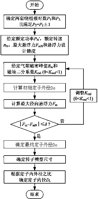
[0013] The present invention introduces the magnetic field dichotomy coefficient K red , through repeated iterations to obtain the magnetic field dichotomy coefficient that satisfies the required maximum levitation force K red , so as to determine the outer diameter of the stator of the induction bearingless motor D o , on this basis, the slot size of the rotor and the inner diameter of the stator can be determined D i and other main structural parameters. Such as figure 1 Shown, the present invention is specifically implemented according to the following steps:

[0014] Step 1: According to the actual design requirements of the induction type bearingless motor, select the two sets of torque winding pole pairs of the induction type bearingless motor, and the number of torque winding pole pairs P 1 and the force pole pairs of the suspension winding P 2 , and satisfy P 2 = P 1 ±1. Selected induction type bearingless motor rated power P N ',Rated speed n N , ...


PUM


Abstract

The invention discloses an induction type bearing-free motor optimization design method based on the dichotomy. An air gap flux density peak value B1m generated by a torque winding and an air gap flux density peak valve B2m generated by a floating force winding are used for calculating a dichotomy coefficient Kred of a magnetic field. The initial outer diameter of a stator and the maximum floating force are calculated out. The maximum floating force Fm and the maximum floating force reference value FmN are compared. The final maximum floating force Fm conforming to the requirement is determined through repeated dichotomy by changing the dichotomy coefficient Kred of the magnetic field according to a precision requirement. Thus, the final outer diameter Do of the stator is determined. The proportion of iron and copper in use is further optimized, the size of a motor is reduced, the maximum torque of the motor can be used as starting torque and the starting performance of the motor is not a big concern. Thus, a rotor groove is further optimized in design and better operation performance is obtained.

Description

technical field [0001] The invention belongs to the design field of magnetic levitation transmission / driving devices, and in particular relates to an optimal design method of an induction type bearingless motor. Background technique [0002] Induction bearingless motor (also known as induction magnetic levitation motor) integrates the rotation function of traditional induction motor and the levitation function of magnetic levitation bearing. It is a new type of magnetic levitation transmission / drive device. have a broad vision of application. [0003] In the induction bearingless motor, there are magnetic fields generated by the two sets of windings, the electromagnetic torque winding and the suspension force winding, and the currents of the two windings respectively generate induced currents in the magnetic field of the other, so the magnetic field distribution of the motor is very complicated; the most important The most important thing is that not only the torque require...

Claims


Application Information

Patent Timeline
Patent Type & Authority Applications(China)
IPC IPC(8): H02K15/02
Inventor 杨泽斌孙晓东李可汪明涛董大伟朱熀秋
Owner 江阴智产汇知识产权运营有限公司
Why Eureka
Try Eureka