
Pipeline machine

A pipeline machine and reed switch technology, which is applied in the field of pipeline machines, can solve the problems of water bag water bag damage, trouble, manual discharge of water bags, etc., and achieve the effect of reducing manufacturing costs, reducing manufacturing costs, and preventing secondary pollution

Active Publication Date: 2013-12-04
江苏正本净化节水科技实业有限公司
View PDF10 Cites 14 Cited by
  • Summary
  • Abstract
  • Description
  • Claims
  • Application Information

AI Technical Summary

Problems solved by technology

However, because the water bag is very thin, it is easy to be injured and leaks, and every time the water bag is filled with water, it will cause slight damage to the water bag
In addition, the material of the water bag itself will lose its flexibility due to gradual aging and cause rupture
Once broken, even a small break can cause a leak
In addition, certain gas will always be dissolved in drinking water at normal temperature, and the gas dissolved in the water will escape due to temperature changes or pressure changes. Since the water bag is airtight, the escaping gas will gradually increase in the water bag and Occupies the inner space of the water bag, causing the water storage capacity of the water bag to decrease, so after a period of use, the gas in the water bag needs to be manually discharged, which adds trouble to the user

Method used


Image

  • Pipeline machine
  • Pipeline machine
  • Pipeline machine

Examples


Embodiment 1)

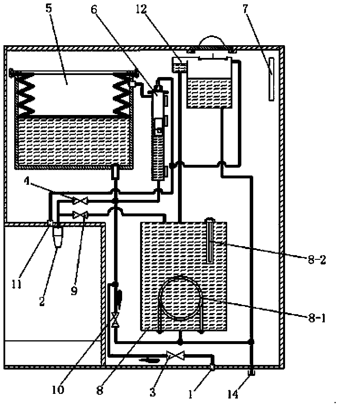
[0032] See Figure 1 to Figure 4 , the pipeline machine of this embodiment is characterized in that it includes a water inlet 1, a water outlet 2, a water inlet valve 3, a normal temperature water outlet valve 4, a diaphragm type water storage tank 5, a water level detector 6, an electrical control circuit board 7, a heat Tank 8, hot water outlet valve 9, hot tank water inlet check valve 10, exhaust port 11, expansion tank 12, sewage outlet 14 and water outlet electrical switch.

[0033] The water inlet 1 is connected to the inlet of the water inlet valve 3 , and the outlet of the water inlet valve 3 is connected to the diaphragm type water storage tank 5 . The inlet of the normal temperature water outlet valve 4 is connected to the bottom of the diaphragm type water storage tank 5 , and the outlet of the normal temperature water outlet valve 4 is connected to the water outlet 2 . The water level detector 6 is used to detect the water level in the diaphragm type water storage...

Embodiment 2)

[0046] See Figure 5 , this embodiment is basically the same as Embodiment 1, except that: the water level detector 6 is arranged inside the water storage tank 5 .

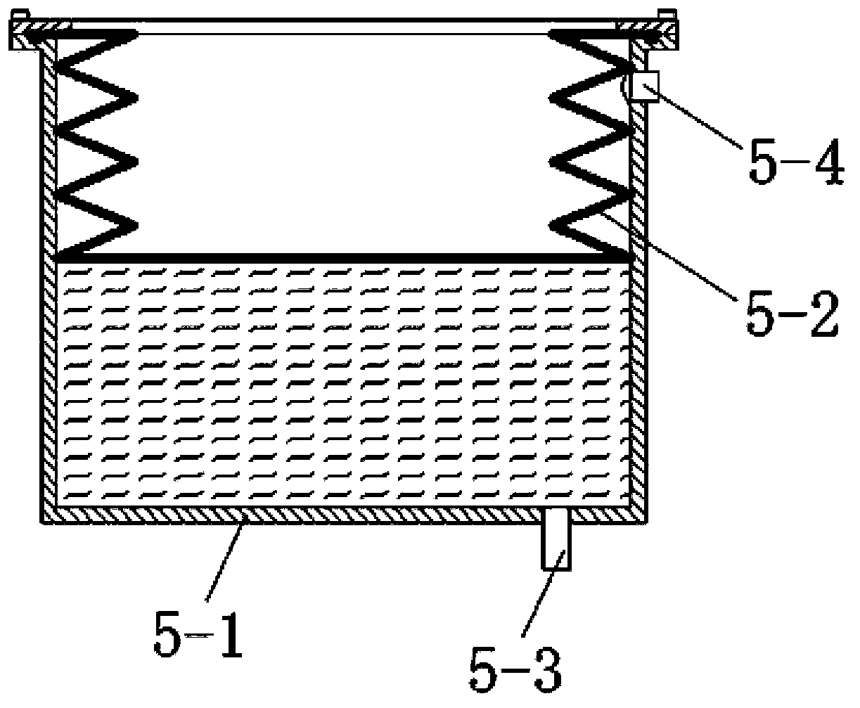
[0047] The top of the diaphragm type water storage tank is provided with a water tank exhaust port 5-4, and the water tank exhaust port 5-4 communicates with the exhaust port 11 through a one-way valve 13.


PUM


Abstract

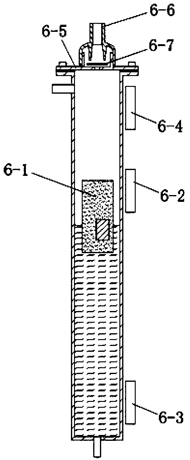
The invention discloses a pipeline machine which comprises a water inlet, a water outlet, a water inlet valve, a normal temperature water outlet valve, a membrane-type water storage tank, a water level detector and an electrical control circuit board; the water inlet is communicated with an inlet of the water inlet valve, and an outlet of the water inlet valve is communicated with the membrane-type water storage tank; an inlet of the normal temperature water outlet valve is communicated with the bottom of the membrane-type water storage tank, and an outlet of the normal temperature water outlet valve is communicated with the water outlet; the water level detector is used for detecting the water level in the membrane-type water storage tank; a magnetic floater capable of lifting along with the rising and falling of the water level is arranged in the water level detector, and a reed pipe is arranged outside the water level detector; the electrical control circuit board is electrically linked with the reed pipe. According to the pipeline machine, the membrane-type water storage tank is adopted, secondary pollution to drinking water can be prevented effectively, meanwhile, due to the fact that a membrane of the membrane-type water storage tank does not contain water, requirements for intensity of the membrane are reduced, the membrane is not damaged easily, and even though the membrane is damaged, leakage of the pipeline machine does not occur.

Description

technical field [0001] The present invention relates to pipeline machines. Background technique [0002] The pipeline machine is usually used in conjunction with the water purifier. When the water flow rate of the water purifier is too small to meet the user's water intake flow requirements, it is necessary to add a water storage device to the pipeline machine, usually with a built-in water storage tank, to meet the user's water intake. high flow requirements. The water storage device is generally a normal pressure water storage tank, and communicated with the atmosphere, which solves the problem of water flow. However, it makes it easy for the dust and bacteria in the air to enter the atmospheric water storage tank with the air and pollute the drinking water in it. This is the secondary pollution problem of the pipeline machine. [0003] In order to solve the secondary pollution problem, people think of adopting airtight normal pressure water storage bag to replace normal...

Claims


Application Information

Patent Timeline
Patent Type & Authority Applications(China)
IPC IPC(8): A47J31/46A47J31/44
Inventor 徐立农黄樟焱
Owner 江苏正本净化节水科技实业有限公司
Learn More