Placement structure for getter of double-vacuum layer glass and manufacturing method of placement structure

A technology of vacuum glass and getter, which is applied in glass forming, glass reshaping, glass manufacturing equipment, etc. It can solve the problems of complex encapsulation and placement of getter, difficulty in placing getter, and small getter dose and other problems, to achieve the effect of simple structure, low cost and high vacuum degree

Inactive Publication Date: 2013-12-04
戴长虹
View PDF6 Cites 3 Cited by
  • Summary
  • Abstract
  • Description
  • Claims
  • Application Information

AI Technical Summary

Problems solved by technology

Due to the small space in the vacuum layer of vacuum glass and the transparency of the glass, the protection and activation of the getter needs to be considered, so it is very difficult to place the getter in the vacuum layer
The traditional method of placing the getter in the vacuum glass is to first package the getter under vacuum, and then place it in the groove pre-opened on the glass. After sealing the edge of the vacuum glass, vacuuming, and sealing the suction port , and then use laser or infrared rays to open the package of the getter to activate the getter. The disadvantage of this method is that the encapsulation and placement process of the getter is complicated, the amount of the getter is small, and the appearance and mechanical properties of the glass are affected.

Method used


Image

  • Placement structure for getter of double-vacuum layer glass and manufacturing method of placement structure

Examples


Embodiment

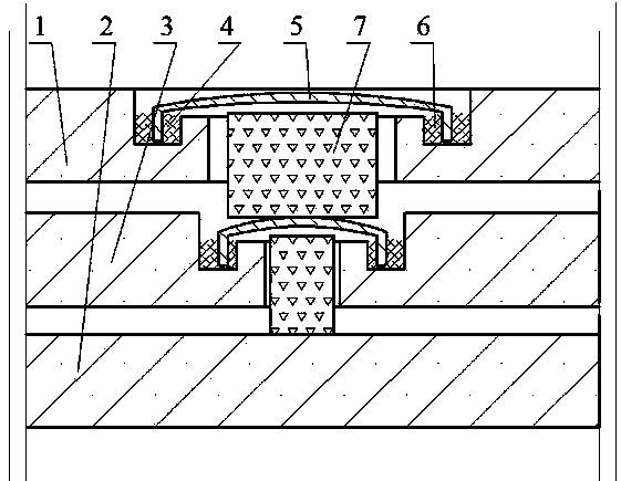
[0042] Embodiment: Referring to the accompanying drawings, the vacuum glass is composed of an upper glass 1, a lower glass 2 and a middle glass 8. A through hole is respectively drilled on the upper glass 1 and the middle glass 8 to form a suction port, wherein the through hole on the upper glass 1 is larger than the middle glass. A through hole on the glass 8; on the upper surface of the upper glass 1 and the middle glass 8, a hollow drill is used to make a U-shaped sealing groove 4 concentric with the air inlet, and the inner edge of the sealing groove 4 is lower than the upper surface of the upper glass 1. surface; respectively make a seal cover 5 according to the size of the seal groove 4, the edge of the seal cover 5 can be inserted in the seal groove 4, the height of the seal cover 5 is lower than the upper surface of the upper glass 1, the gap between the seal cover 5 and the seal groove 4 The space between them is an air extraction channel; temper the upper and lower gl...


PUM


Abstract

A placement structure for getter of double-vacuum layer glass is characterized in that openings are formed in upper glass and middle glass of vacuum glass to serve as exhaust openings, two seal grooves are formed in the upper surfaces of the upper glass and the middle glass respectively, and surround the respective exhaust openings; seal covers are arranged on the seal grooves, and the edges of the seal covers are inserted into the seal grooves respectively; after edge sealing for the glass, the getter is placed into the exhaust openings, the exhaust openings are covered with the seal covers, and metal solder is placed inside the seal grooves or on the seal covers; then vacuumizing and heating are performed on a vacuum heating furnace, so that the getter can be activated automatically under the high-temperature and high-vacuum condition, and meanwhile, the metal solder is molten to be liquid due to the high temperature; the liquid is stored in the seal grooves, and the edges of the seal covers are immersed in the liquid, so that the exhaust openings are automatically sealed and the getter is sealed in the vacuum layers by utilizing the liquid sealing principle; after the liquid is solidified due to temperature drop, the airtight sealing is realized. With adoption of the method disclosed by the invention, batch production can be realized, production efficiency and qualification rate of the vacuum glass can be greatly improved, and production cost is lowered.

Description

technical field [0001] The invention belongs to the field of vacuum glass, and in particular relates to a placement structure of a double-vacuum layer glass getter and a manufacturing method thereof. [0002] Background technique [0003] The existing vacuum glass is generally composed of two or three pieces of flat glass. The glass is sealed with low-temperature glass solder around the edges, and there is a tiny support in the middle. A thin layer of 0.1-0.2mm thickness is formed between the two pieces of glass by pumping air. Vacuum layer. Since there is no heat and sound transmission of gas, and the inner surface of the glass can have a transparent low-heat radiation film, the vacuum glass has good heat insulation and sound insulation effects, and is one of the best performance energy-saving glasses. [0004] The key technologies of the existing vacuum glass include: one is edge sealing, the other is the placement of supports, and the third is the acquisition and mainte...

Claims


Application Information

Patent Timeline
Patent Type & Authority Applications(China)
IPC IPC(8): C03B23/24C03C27/08
CPCY02P40/57
Inventor 戴长虹
Owner 戴长虹
Why Eureka
Try Eureka