Rotor and rotating electrical mechanism using same

一种电气机械、转子的技术,应用在转子领域,能够解决成本增加等问题,达到组装容易、稳定运转、解决消磁问题的效果

Active Publication Date: 2013-12-04
DAIKIN IND LTD
View PDF5 Cites 10 Cited by
  • Summary
  • Abstract
  • Description
  • Claims
  • Application Information

AI Technical Summary

Problems solved by technology

However, this solution has the problem of increased cost

Method used


Image

  • Rotor and rotating electrical mechanism using same
  • Rotor and rotating electrical mechanism using same
  • Rotor and rotating electrical mechanism using same

Examples


no. 1 approach 》

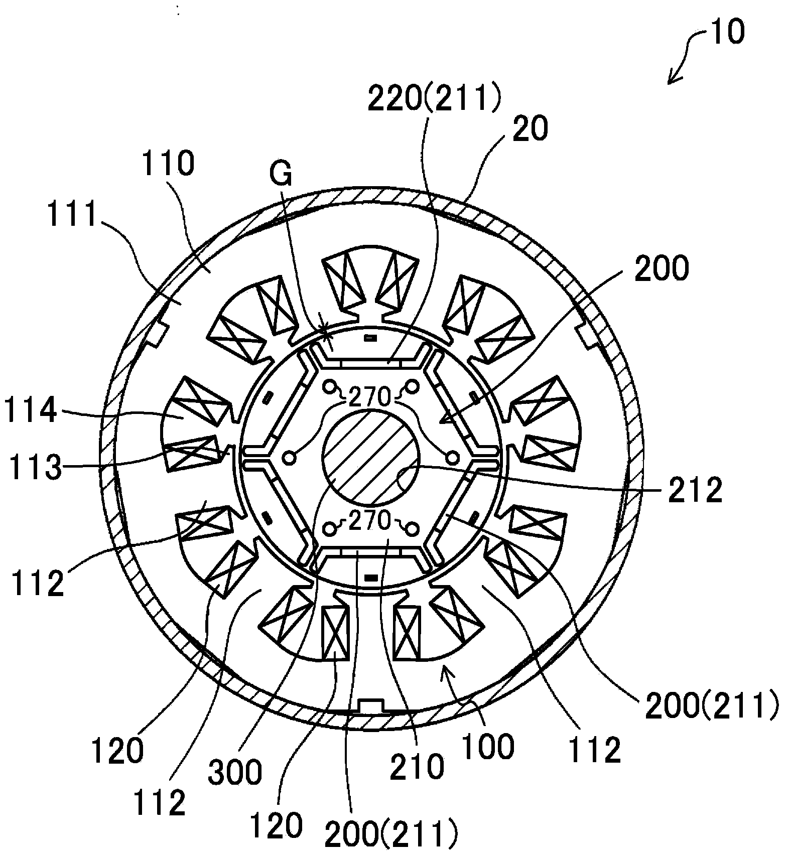
[0053] figure 1 It is a transverse cross-sectional view of the motor 10 according to the first embodiment of the present invention. This motor 10 is used, for example, in an electric compressor of an air conditioner (illustration omitted).

[0054]

[0055] motor 10 as figure 1As shown, a stator 100 , a rotor 200 , and a drive shaft 300 are provided, which are housed in the casing 20 of the above-mentioned electric compressor. In addition, in the following description, the axial direction refers to the direction of the axis of the drive shaft 300 , and the radial direction refers to a direction perpendicular to the axis. In addition, the outer peripheral side refers to the side relatively far from the above-mentioned axis, and the inner peripheral side refers to the side relatively close to the above-mentioned axis.

[0056]

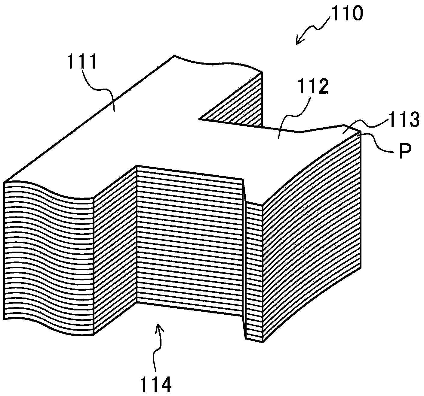
[0057] like figure 1 As shown, the stator 100 includes a cylindrical stator core 110 and a coil 120 .

[0058] The stator core 110 is a laminat...

no. 2 approach 》

[0087] Figure 10 It is a sectional view of the rotor 200 according to the second embodiment of the present invention. The rotor 200 of the present embodiment includes one first rotor core 240 and one second rotor core 250 . Also in this example, the height H1 (the aforementioned axial dimension) of the first rotor core 240 is smaller than the height H2 of the second rotor core 250 . The first rotor core 240 and the second rotor core 250 are connected to each other at axial ends.

[0088] With such a configuration, even in the present embodiment, even if a reverse magnetic field acts on the rotor 200 , most of the magnetic flux flows toward the magnetic core portion 240 a on the first rotor core 240 side. Therefore, in the present embodiment, the problem of demagnetization can be solved on the first rotor core 240 side of each permanent magnet 220 . In addition, the second rotor core 250 can easily insert the permanent magnet 220 into the magnet groove 211 from the axial en...

no. 3 approach 》

[0090] Figure 11 It is a sectional view of the rotor 200 according to the third embodiment of the present invention. The rotor 200 of this embodiment includes one first rotor core 240 and two second rotor cores 250 . The rotor 200 of the present embodiment is formed by sandwiching the second rotor core 250 from both axial ends of the first rotor core 240 . Also in this example, the height H1 (the aforementioned axial dimension) of the first rotor core 240 is smaller than the height H2 of the second rotor core 250 .

[0091] With such a configuration, even in the present embodiment, even if a reverse magnetic field acts on the rotor 200 , most of the magnetic flux flows toward the magnetic core portion 240 a on the first rotor core 240 side. Therefore, the problem of demagnetization of the permanent magnet 220 can be solved in the vicinity of the axial center portion of the rotor 200 where a relatively strong reverse magnetic field tends to act.

[0092] In addition, in thi...


PUM


Abstract

The purpose of the present invention is to provide a rotating electrical mechanism comprising a rotor having rotor cores onto which magnets have been mounted, wherein demagnetization of the magnets can be counteracted while a decline in the performance of the rotating electrical mechanism is suppressed. This rotor is provided with: first rotor cores (240) comprising a plurality of spaces (241) extending through in the axial direction; and a second core (250) in contact with the axial ends of the first rotor cores (240), the second core being provided with a plurality of magnet slots (211) at positions facing the spaces (241). The spaces (241) are formed with a lower magnetic resistance than the magnet slots (211). This configuration makes it possible to reduce the intensity of the reverse magnetic field acting on permanent magnets (220), and to cause a reluctance torque to be generated by the first rotor cores (240). Therefore, demagnetization of the magnets can be counteracted while a decline in performance can be suppressed in a rotating electrical mechanism comprising a rotor having rotor cores onto which magnets have been mounted.

Description

technical field [0001] The present invention relates to a rotor having a rotor core to which magnets are mounted; and a rotating electric machine using the rotor. Background technique [0002] A rotating electrical machine such as a magnet-assisted synchronous reluctance motor (SynRM for short) or an interior permanent magnet motor (Interior Permanent Magnet for short: IPM motor) has a rotor core to which magnets are mounted. In such a rotating electric machine, for some reason, a large reverse magnetic field is applied from the stator to the permanent magnet of the rotor core, and the magnetic force of the permanent magnet is demagnetized. For this problem, for example, it can be solved by increasing the thickness of the magnet. However, this solution has a problem of increased cost. [0003] There is also an example of trying to solve the problem of degaussing by adjusting the magnetic circuit of the magnetic flux (for example, refer to Patent Document 1). In this examp...

Claims


Application Information

Patent Timeline
Patent Type & Authority Applications(China)
IPC IPC(8): H02K1/27H02K1/22H02K19/10
CPCH02K1/246H02K1/276H02K1/2766H02K2213/03
Inventor 近藤俊成安田善纪山际昭雄
Owner DAIKIN IND LTD
Why Eureka
Try Eureka