Horizontal and vertical comprehensive utilization of floating body rope wheel power generation system

A horizontal and vertical power generation system technology, applied in ocean energy power generation, engine components, machines/engines, etc., can solve the problems of scattered core components, low energy utilization rate, high installation cost, etc., and achieve easy maintenance and high energy utilization rate , low cost effect

Inactive Publication Date: 2015-12-02
SHANDONG UNIV
View PDF5 Cites 2 Cited by
  • Summary
  • Abstract
  • Description
  • Claims
  • Application Information

AI Technical Summary

Problems solved by technology

[0017] In addition, the core components of the existing scheme are scattered, the installation cost is high, and it is not conducive to maintenance. The floating body rope wheel power generation system in the prior art has only one vertical rope, and there is no constraint in the horizontal direction, which is easy to cause deviation from the allowable range due to the action of wind and sea current , and the existing technology only uses the vertical rise and fall of waves to generate power, and the energy utilization rate is low

Method used


Image

  • Horizontal and vertical comprehensive utilization of floating body rope wheel power generation system
  • Horizontal and vertical comprehensive utilization of floating body rope wheel power generation system
  • Horizontal and vertical comprehensive utilization of floating body rope wheel power generation system

Examples


Embodiment Construction

[0030] The present invention will be further described in detail below in conjunction with the drawings:

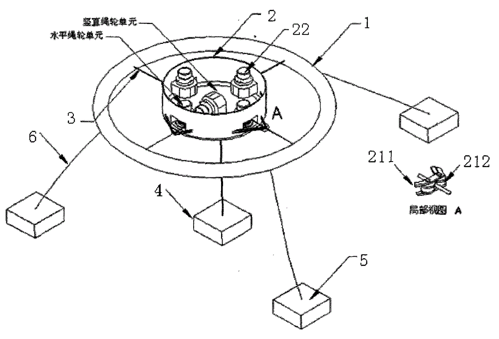
[0031] Such as figure 1 Shown is a schematic diagram of the overall structure of the present invention. For clarity of description, only the related structure of the technical solution of the present invention will be described. A horizontal and vertical integrated use of floating body rope wheel power generation system includes a hollow floating body 1 located on the same plane as the floating body 1 The generator nacelle 2 in the center is connected to the floating body 1 by a plurality of ropes 3 diagonally arranged on the inner side of the floating body 1. The generator nacelle 2 is fixed with an anchor base 4 on the seabed vertically below the generator nacelle 2 and the anchor The base 4 is connected by a rope 3, a plurality of fixed floating body anchor bases 5 are arranged around the floating body 1, and the floating body anchor base 5 is connected to the outside of t...


PUM


Abstract

A generating system horizontally, vertically, and comprehensively utilizing floating body rope wheel comprises a hollow floating body and a generating cabin located in the center of the floating body and located on the same plane as the floating body. The generating cabin is connected with the floating body through a plurality of ropes connected to the inner side of the floating body and arranged in diagonal mode. An anchoring base is fixed on the sea bed perpendicularly under the generating cabin. The generating cabin is connected with the anchoring base through a rope. A plurality of fixed floating body anchoring bases are arranged on the periphery of the floating body and are connected with the outer side of the floating body through lock chains. The generating system can sufficiently utilize energy in the horizontal direction and the vertical direction of waves to generate electricity and is high in energy utilization rate. Moreover, a generator is embedded in a coiling block, and the coiling block drives, through an overrunning coupler, a minimai promoter shell to rotate, so that rotating inertia can be reduced to a largest degree, and the service life of the whole equipment can be improved. Core parts are all contained in the coiling block, so that the generating system has the advantages of being compact in structure, easy to manufacture in a modularized mode, low in cost, and favorable to maintenance.

Description

Technical field [0001] The invention relates to the field of wave power generation, in particular to a horizontal and vertical comprehensive utilization of floating body rope wheel power generation system. Background technique [0002] Now with the reduction of fossil energy and the environmental pollution caused by it, the development of renewable energy is becoming more and more important. Wave energy can reach several Kw to several tens of Kw per meter, which is the energy density of renewable energy. One, therefore, wave power is a very good choice in islands and coastal cities. [0003] The existing wave generators include the following: [0004] "Nodding duck" style [0005] The "nodding duck" wave energy generating device is named because the shape and operating characteristics of the device resemble the movement of a duck. The movement of the incident wave makes the dynamic pressure push the rotating part to rotate around the axis, and the change of hydrostatic pressure makes...

Claims


Application Information

Patent Timeline
Patent Type & Authority Patents(China)
IPC IPC(8): F03B13/18
CPCY02E10/30
Inventor 朱林森李保国曲言明王延刚杨泽刘彬苏斌
Owner SHANDONG UNIV
Why Eureka
Try Eureka