Rotational clap suction/pressure device
A rotating ground, rotating pin technology, used in rotary piston engines, rotary or oscillating piston engines, rotary piston pumps, etc., can solve problems such as low durability and efficiency
- Summary
- Abstract
- Description
- Claims
- Application Information
AI Technical Summary
Problems solved by technology
Method used
Image
Examples
no. 1 example
[0106] Now, four blades 1143115311401150 are respectively provided on the first rotary piston and the second rotary piston in the rotary flap suction device 1100 according to the first embodiment of the present invention.
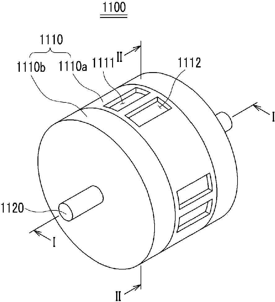
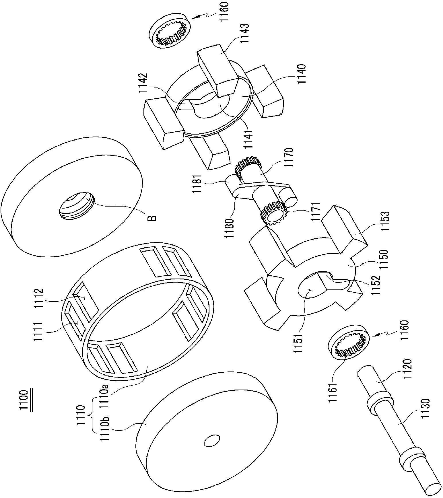
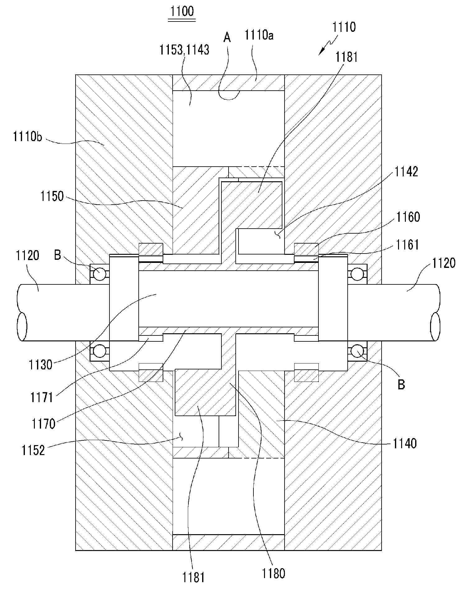
[0107] Such as Figure 1 to Figure 8 As shown, the rotary flap suction device 1100 of the first embodiment of the present invention includes: a cylindrical housing 1110, which is provided with four suction inlets 1111 and discharge outlets 1112 on its housing cylinder 1110a at a predetermined distance. housing side plates 1110b are mounted on both sides of the housing cylinder 1110a; a crankshaft 1120 configured to operate a central portion of the housing side plate 1110b is rotatably supported by the cylindrical housing 1110; crank pin 1130 is eccentric to said crankshaft 1120 so as to extend from a central portion of said crankshaft 1120; a first rotary piston 1140 rotatably mounted within said cylindrical housing 1110 has a shaft drive hole at a central ...
no. 2 example
[0120] The rotary flapping pressure suction device 2100 of the second embodiment of the present invention will be described below.
[0121] The rotary flapping pressure suction device 2100 of the second embodiment of the present invention is described for the structure in which three vanes 1143 and 1153 are respectively provided on the first rotary piston 1140 and the second rotary piston 1150 . Wherein, since the rotary flap suction pressure device 2100 of the second embodiment of the present invention has the same structure as the aforementioned rotary flap suction pressure device 1100 of the first embodiment of the present invention except for the number of blades, therefore, in order to illustrate For convenience, the same reference symbols are given to the same elements.
[0122] Such as Figure 10 As shown in a-e, when the number of each of the blades 1143, 1153 is three, the gear ratio of the fixed internal gear 1161 to the planetary external gear 1171 is set to 3:2. ...
no. 3 example
[0125] The rotary flap suction device 3100 of the third embodiment of the present invention describes the structure in which two vanes 11431153 are respectively provided on the first rotary piston 1140 and the second rotary piston 1150 . Among them, the rotary flapping pressure suction device 3100 of the third embodiment of the present invention has the same structure as the aforementioned rotary flapping pressure suction device 1100 of the first embodiment of the present invention except for the number of blades, therefore, for the convenience of description For the same constituent elements, the same reference symbols are given.
[0126] Such as Figure 11 As shown in a-e, when each of the blades 1143, 1153 is 2, the gear ratio of the fixed internal gear 1161 to the planetary external gear 1171 is set to 3:2.
[0127] When the crankshaft 1120 rotates clockwise at a constant speed by a motor (not shown) as a power source, the rotation pin 1181 of the connecting rod 1180 rota...
PUM
 Abstract
Description
Claims
Application Information
 - R&D
- Intellectual Property
- Life Sciences
- Materials
- Tech Scout
- Unparalleled Data Quality
- Higher Quality Content
- 60% Fewer Hallucinations
Browse by: Latest US Patents, China's latest patents, Technical Efficacy Thesaurus, Application Domain, Technology Topic, Popular Technical Reports.
© 2025 PatSnap. All rights reserved.Legal|Privacy policy|Modern Slavery Act Transparency Statement|Sitemap|About US| Contact US: help@patsnap.com


