Flue gas purifying system

A flue gas purification system and flue gas technology, applied in the direction of chemical instruments and methods, dispersed particle separation, combined devices, etc., can solve the problems of adsorption tower damage, combustion, activated carbon or activated coke failure, etc., to avoid failure and avoid partial hotspot effect

Inactive Publication Date: 2013-12-18
HONGKONG NOROTAEIL ENVIROMENTAL PROTECTION TECH CO +1
View PDF7 Cites 21 Cited by
  • Summary
  • Abstract
  • Description
  • Claims
  • Application Information

AI Technical Summary

Problems solved by technology

[0003] The system uses activated carbon or activated coke to purify the flue gas, but because the flue gas itself has a high temperature, and the flue gas is reheated after being adiabatically compressed by the fan, when the temperature of the flue gas entering the adsorption tower exceeds At 150°C, the activated carbon or activated c

Method used


Image

  • Flue gas purifying system
  • Flue gas purifying system
  • Flue gas purifying system

Examples


Embodiment Construction

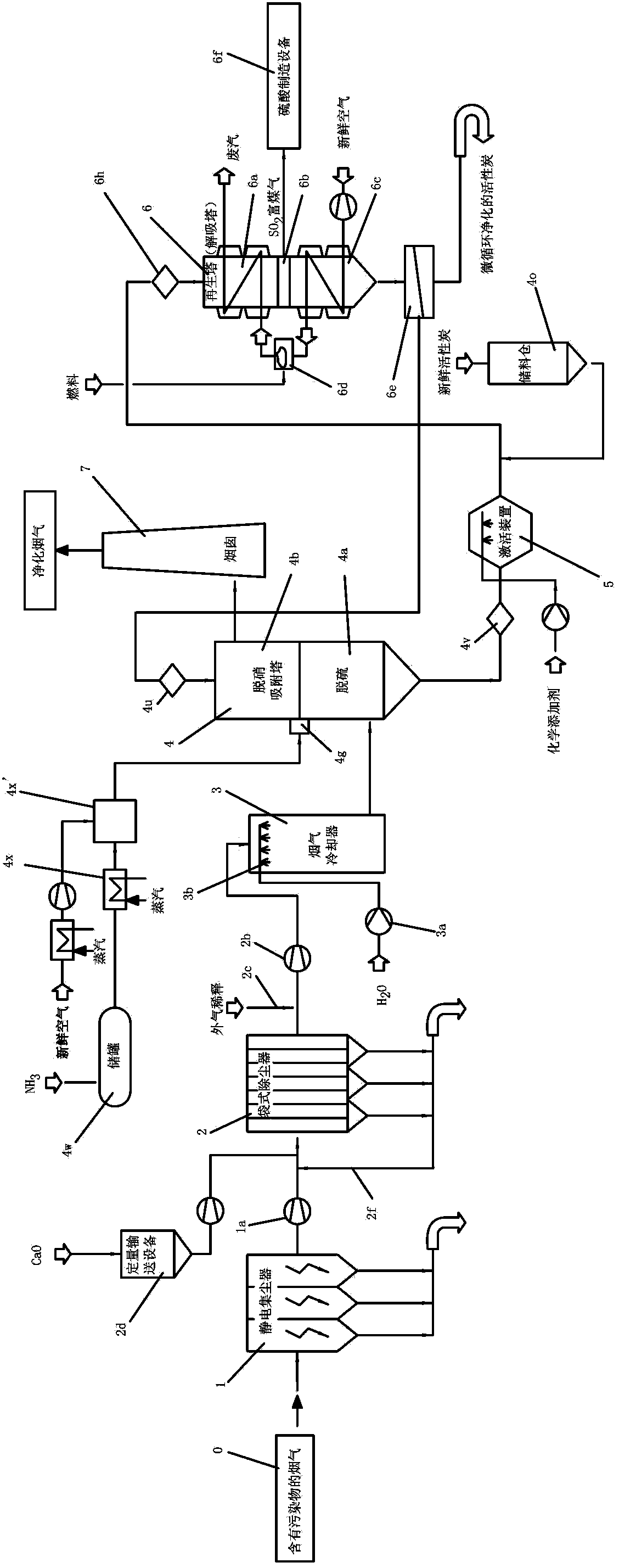
[0034] The flue gas purification system is to remove the sulfur oxides and nitrogen oxides contained in the flue gas produced by the sintering process of ironworks or the combustion of fossil fuels and their compounds in coal-fired power plants, or the flue gas emitted by incinerators. , tribute, dioxin / furan and integrated systems for dust capture and removal, such as figure 1 As shown, the flue gas purification system of the present invention includes a pretreatment system, a flue gas cooling system, an adsorption tower, a regeneration tower 6, an activation device 5, a dust removal system, and a fresh activated carbon storage bin 4o. The flue gas enters the adsorption system through a pipeline through the pretreatment system After the tower 4 is purified, the purified flue gas is discharged from the chimney 7.

[0035] The pretreatment system of the present invention includes an electrostatic precipitator 1 and a first bag filter 2, the electrostatic precipitator 1 is a pri...


PUM

PropertyMeasurementUnit
Diameteraaaaaaaaaa

Abstract

The invention relates to a flue gas purifying system which comprises a pretreatment system, a flue gas cooling system and an adsorbing tower, wherein flue gas enters the adsorbing tower through the pretreatment system by a pipeline and then is purified, the flue gas cooling system is arranged on a pipeline between the pretreatment system and the adsorbing tower, the flue gas cooling system comprises a flue gas cooler, an external gas diluter, a first temperature sensor, a second temperature sensor and a first flue gas pipe; one end of the first flue gas pipe is fixedly arranged on a gas inlet of the adsorbing tower, a gas inlet baffle plate is arranged on the gas inlet of the adsorbing tower, the other end of the first flue gas pipe is connected with the pretreatment system, the external gas diluter and the flue gas cooler are respectively arranged on the first flue gas pipe, the flue gas cooler is positioned between the external air cooler and the adsorbing tower, the first temperature sensor is positioned between the external gas diluter and the flue gas cooler, the second temperature sensor is positioned between the flue gas cooler and the adsorbing tower, and a baffle plate capable of regulating the gas inflow is arranged on the external gas cooler. According to the flue gas purifying system, local hot spots of active carbon or active coke in the adsorbing tower can be prevented.

Description

technical field [0001] The present invention relates to a flue gas purification system, in particular to a sintering process used in metal manufacturing in ironworks or the smoke generated and discharged during the combustion of fossil fuel (coal) / coke or its compounds in thermal power plants Gas, or a purification system for the flue gas emitted during the incineration of industrial / domestic waste. Background technique [0002] In the sintering process in metal manufacturing in ironworks or in the flue gas generated and discharged during the combustion of fossil fuel (coal) / coke or its compounds in thermal power plants, or in the flue gas emitted during the incineration of industrial / domestic waste, The pollution sources such as SOx (sulfur oxides), NOx (nitrogen oxides), heavy metals (heavy metals containing tribute), dioxins / furans, etc. have caused serious pollution to the environment. In order to reduce the pollution of the above flue gas to the environment, the prior ...

Claims


Application Information

Patent Timeline
IPC IPC(8): B01D50/00B01D53/86B01D53/56
Inventor 王建辉
Owner HONGKONG NOROTAEIL ENVIROMENTAL PROTECTION TECH CO
Why Eureka
Try Eureka