
Heat conduction block

A technology of heat conduction block and heat conduction column, which is applied in the direction of conductors, non-insulated conductors, heating or cooling equipment, etc., which can solve the problems of high production cost, high metal cost, burns of users, etc., and achieve less injury or discomfort, and skin temperature The effect of low change amount and reduced energy loss

Inactive Publication Date: 2013-12-18
易春 +1
View PDF0 Cites 0 Cited by
  • Summary
  • Abstract
  • Description
  • Claims
  • Application Information

AI Technical Summary

Problems solved by technology

The disadvantages of using a metal block as a heat conduction block are:
[0004] 1. It is easy for the user to touch the surface of the metal block when placing the test tube into or removing it from the metal block. When the temperature of the metal block is high or low, it may cause discomfort to the user, and may even be harmful to the user. Deals burn or frostbite damage
[0005] 2. The surface of the metal block will lose heat energy to the surrounding environment
[0007] 4. The production cost is high, this is because the cost of the metal itself is high, and the production cost of multiple processing procedures is also high
[0008] 5. The metal block is very heavy. If copper or silver is used as the material, the weight will be even greater

Method used


Image

  • Heat conduction block
  • Heat conduction block
  • Heat conduction block

Examples


Embodiment approach 1

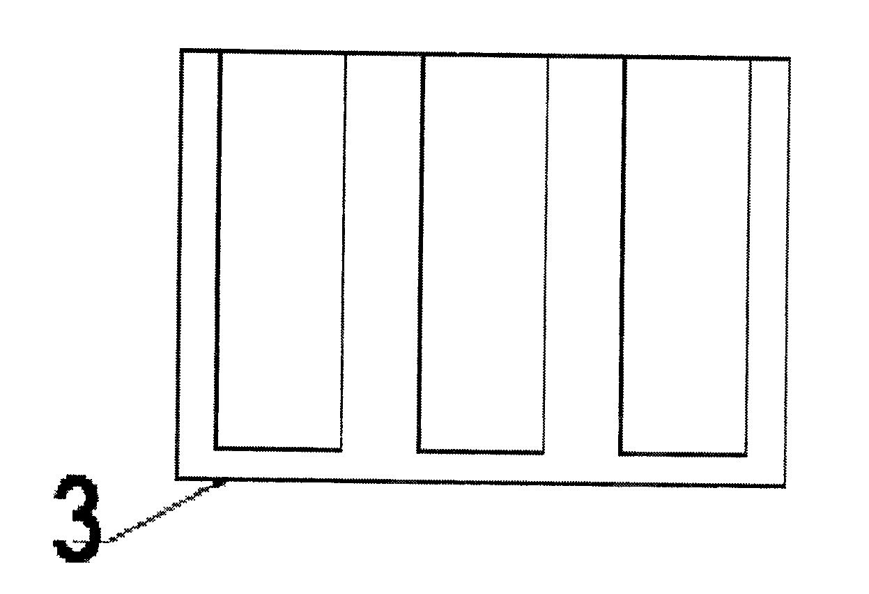
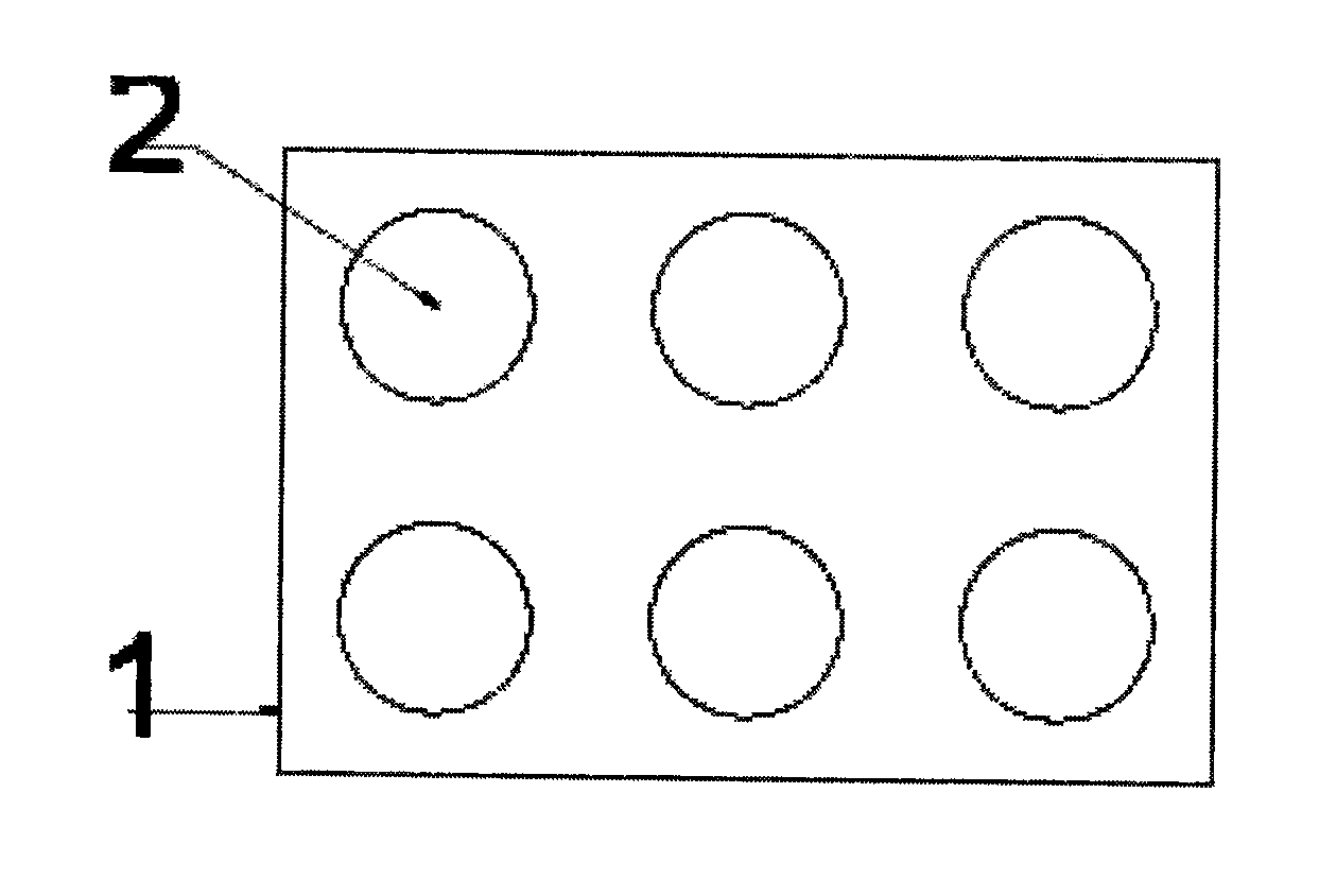
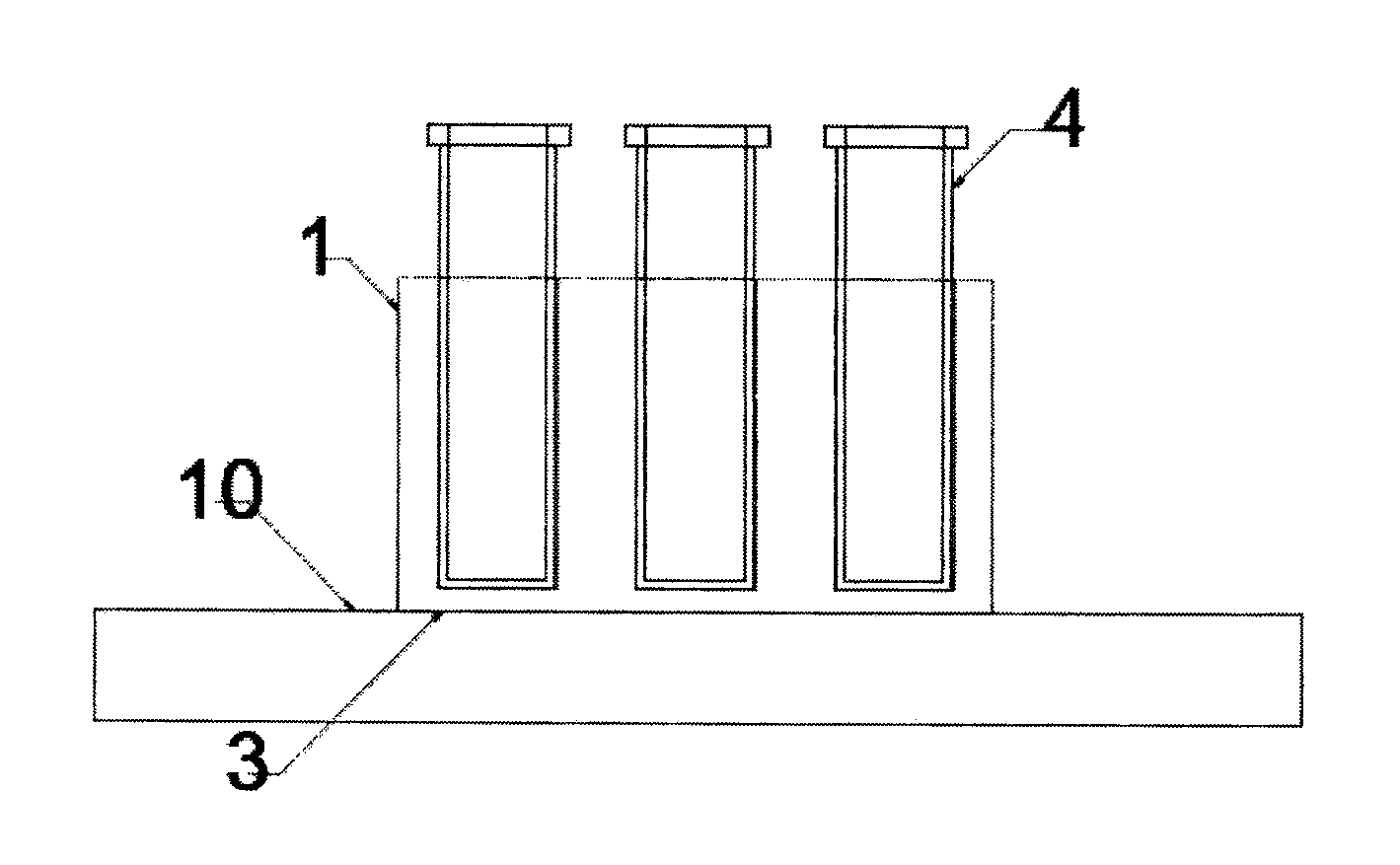
[0043] Embodiment 1: A heat conduction block 1, the heat conduction block 1 is composed of two parts, the first part is a heat conduction column 5, and the heat conduction column 5 is a cylindrical structure made of a material with high thermal conductivity, and the heat conduction column One end face of the cylinder is a plane, and the plane is connected to the heat source plane. The other end of the heat conduction cylinder has a conical or cylindrical hole 7, and the surface of the conical hole or cylindrical hole is connected to the outside of the test tube. In cooperation, the second component is a frame mechanism made of a material with low thermal conductivity, the frame structure has one or more through holes, and the heat conducting column can be placed in the through holes of the frame mechanism.

[0044] The frame of this embodiment is made of solid silicone rubber material, usually in a scale press vulcanization process. The heat conduction column is made of alumin...

Embodiment approach 2

[0048] Embodiment 2: The heat conduction column has a flange edge. The frame is made of silicone rubber material, usually made by large-scale pressure vulcanization process. The heat conduction column is made of aluminum alloy through turning. The diameter of the flange side of the heat conduction column is slightly larger than the diameter of the mounting hole of the frame under natural conditions. When the heat conduction column is installed, the inner wall of the frame mounting hole is subjected to the radial force of the flange edge of the heat conduction column, and its diameter is enlarged, so that the heat conduction column can penetrate the heat conduction hole. After the heat conduction column penetrates, the diameter of the installation hole returns to the natural state, and the flange of the heat conduction column plays the role of fixing the heat conduction column to the frame installation hole. Embodiment 2 has two kinds of heat conduction columns, the differenc...


PUM


Abstract

The invention discloses a heat conduction block, and is characterized in that: the heat conduction block consists of two parts, the first part is heat conduction columns, the heat conduction columns each have a columnar structure made of a high heat conductivity material, an end face of a column body of each heat conductivity column is a plane connected with a plane of a heat source, the other end of the column body of each heat conductivity column is provided with a conical hole or a cylindrical hole, and the surface of the conical hole or the cylindrical hole is matched with the outer surface of a reaction tube; and the second part is a frame structure made of a low heat conductivity material, the frame structure is provided with one or more through holes, and the heat conductivity columns can be placed in the through holes of the frame structure. The heat conduction block reduces the potential safety hazard, reduces the heat capacity, reduces the energy loss, and decreases the manufacturing cost.

Description

technical field [0001] The invention relates to heat conduction technology, in particular to a composite material heat conduction block. Background technique [0002] Almost all biochemical reactions in the laboratory need to be carried out at a specific temperature. In order to maintain the specific temperature required for the reaction, the reaction solution is usually placed in a reaction test tube. In order to maintain the temperature required for the reaction, the test tube needs to be placed in a thermostatically controlled device with heating or cooling capabilities. Common such constant temperature control devices include constant temperature ovens, constant temperature water baths, dry metal baths, etc. Because the operation with dry metal bath is relatively clean, it is not easy to pollute the test tube, and it occupies a small area. Dry metal bath will gradually replace other constant temperature equipment. Because the reaction test tube is generally cylindrical...

Claims


Application Information

Patent Timeline
Patent Type & Authority Applications(China)
IPC IPC(8): B01L7/00H01B5/00
Inventor 易春刘树谟
Owner 易春
Learn More