Optical-mechanical structure for vertical machining center

A vertical, light-mechanical technology, which is applied in the direction of metal processing machinery parts, metal processing, metal processing equipment, etc., can solve the problems of affecting the service life of the light machine, the small internal space of the base, and affecting the processing accuracy, so as to achieve light weight and improve Efficiency and the effect of improving machining accuracy

Inactive Publication Date: 2013-12-18
SHANGHAI BINSHENG ELECTRONICS MACHINERY
View PDF5 Cites 11 Cited by
  • Summary
  • Abstract
  • Description
  • Claims
  • Application Information

AI Technical Summary

Problems solved by technology

[0006] However, the optical machine of the existing vertical machining center adopts a cross structure with the X-axis on the top and the Y-axis on the bottom. The size of the base is small, and the size of the saddle is large. The optical machine is easy to shake and unstable when running, which affects the processing accuracy
In addition, the span of the guide rails in the optical-mechanical three-axis direction of this structure is small, resulting in a narrow space inside the base, making it impossible to install drag chains, grating rulers and other components inside the shield
In addition, the existing optical machine generally adopts a single-sided spiral chip removal structure, which cannot remove chips in time, thus affecting the service life of the optical machine

Method used


Image

  • Optical-mechanical structure for vertical machining center
  • Optical-mechanical structure for vertical machining center
  • Optical-mechanical structure for vertical machining center

Examples


Embodiment Construction

[0032] The present invention will be further described below in conjunction with the accompanying drawings and specific embodiments.

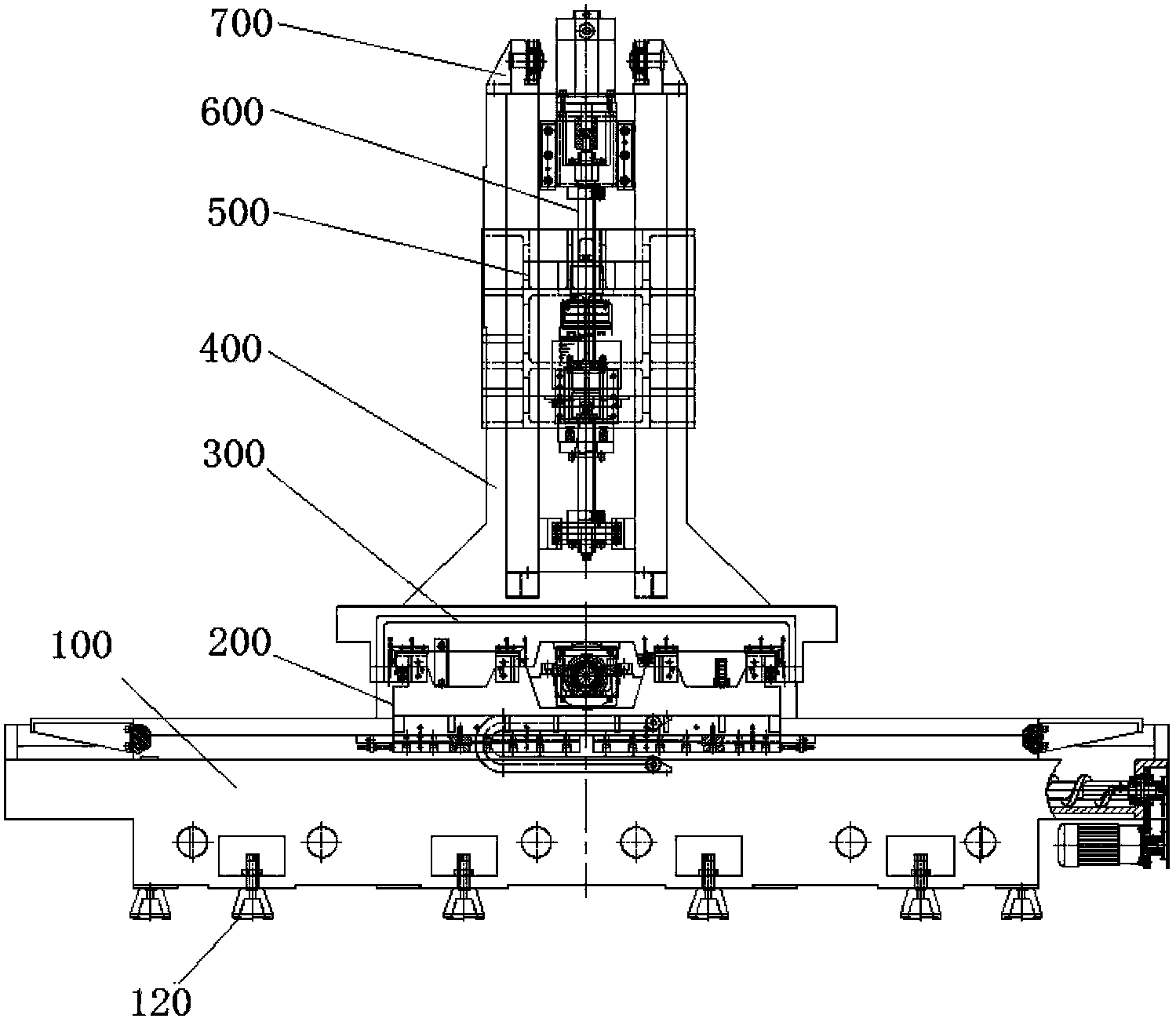
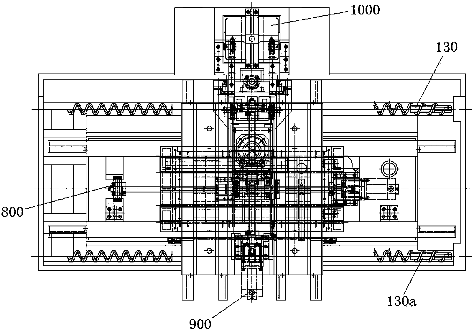
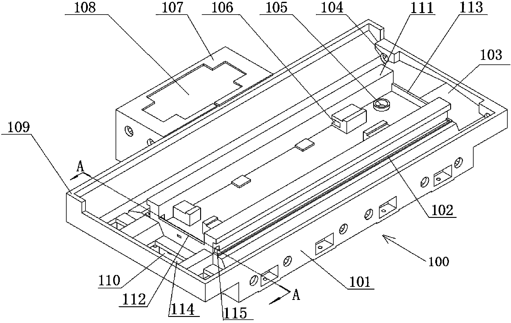
[0033] see figure 1 and figure 2 , the optical-mechanical structure of the vertical machining center shown in the figure includes a bed 100 and a column 400 fixed on the bed 100, a saddle 200, a worktable 300, a spindle box 500, a pulley 700, and an X-axis transmission mechanism 800 , Y-axis transmission mechanism 900, Z-axis transmission mechanism 600, weight balance device 1000, bed foot 120 is installed at the bottom of bed 100, is convenient to adjust the height position and level of bed 100.

[0034] The column 400 is set as the Z-axis, the Z-axis transmission mechanism 600 is installed on the column 400, the spindle box 500 is slidably arranged on the column 400 and connected with the Z-axis transmission mechanism 600, the pulley 700 is fixed on the top of the column 400, and the weight balance device 1000 is arranged on the column 400...


PUM


Abstract

The invention discloses an optical-mechanical structure for a vertical machining center. The optical-mechanical structure comprises a lathe bed, a standing column, a carriage, a workbench, a spindle box, a pulley, an X-axis transmission mechanism, a Y-axis transmission mechanism, a Z-axis transmission mechanism and a counterweight balance device. The standing column and the carriage are fixed on the lathe bed. The Z-axis transmission mechanism is mounted on the standing column. The spindle box is slidably disposed on the standing column and in drive connection with the Z-axis transmission mechanism. The pulley is fixed at the top of the standing column. The counterweight balance device is disposed on the standing column and connected with the spindle box through steel wire rope winding on the pulley. The X-axis transmission mechanism is mounted on the lathe bed. The carriage is slidably disposed on a slide rail of the lathe bed and in drive connection with the X-axis transmission mechanism. The Y-axis transmission mechanism is mounted on the carriage. The workbench is slidably disposed on a slide rail of the carriage and in drive connection with the Y-axis transmission mechanism. The Y-axis transmission mechanism is above the X-axis transmission mechanism. The optical-mechanical structure is shake-free and stable in operation, and accordingly machining precision is increased.

Description

technical field [0001] The invention relates to the technical field of vertical machining centers, in particular to an optical-mechanical structure of a vertical machining center. Background technique [0002] With the rapid development of my country's automobile, mold, aviation, aerospace, electronics, plastics, and alloy industries, traditional manual milling machines can no longer meet the needs of processing and manufacturing industries. Although the number of imports of CNC milling machines and machining centers in my country is increasing year by year, they still cannot meet the needs of the domestic processing industry. Therefore, accelerating the development of domestic CNC milling machines and machining centers with high cost performance is the urgent task and key development direction of domestic professional manufacturers. [0003] Although the specifications, performance, usage and price of vertical machining centers at home and abroad are very different, they a...

Claims


Application Information

Patent Timeline
Patent Type & Authority Applications(China)
IPC IPC(8): B23Q37/00B23Q1/01B23Q11/00B23P23/00
Inventor 李冬
Owner SHANGHAI BINSHENG ELECTRONICS MACHINERY
Why Eureka
Try Eureka