Shear strengthening method of concrete beam

A technology of concrete beams and concrete, applied in bridge reinforcement, bridge, bridge maintenance, etc., can solve the problems of reducing the net height of buildings, accelerated wear and tear of materials, and poor durability, so as to improve the utilization rate of materials, prevent peeling damage, and increase the use value Effect

Inactive Publication Date: 2013-12-18
LIAONING UNIVERSITY OF TECHNOLOGY
View PDF9 Cites 3 Cited by
  • Summary
  • Abstract
  • Description
  • Claims
  • Application Information

AI Technical Summary

Problems solved by technology

[0002] For the shear reinforcement of concrete beams in civil and traffic engineering, the enlarged section method or surface bonding method (abbreviated as EB method) was first adopted, that is, post-cast concrete or adding steel plates, fiber cloth, etc. on the surface of concrete beams. The net height of the building is increased, and the weight of the structure is increased; the EB method is used for reinforcement. Since the reinforcement material is pasted on the surface of the concrete beam and exposed to the air, the durability is poor, and it will inevitably affect the human activity space in buildings with a large flow of people. , the material itself will also accelerate wear
In recent years, the embedding method [abbreviated as NSM method] has developed rapidly. However, this method needs to make grooves on the side of the concrete beam. The thickness of the concrete protective layer of the longitudinal reinforcement is limited. In addition to the construction deviation, it is difficult to ensure the safety of the construction work. Delicate and risk-free, the inevitable damage to the concrete cover of the concrete beam itself is a major drawback of this method
Moreover, in the reinforcement methods of EB method and NSM method, most of the beams are damaged due to the peeling damage between the reinforcement material and the concrete, making it difficult for the reinforcement material to fully exert its shear resistance, and it is also an invisible waste of the material itself.

Method used


Image

  • Shear strengthening method of concrete beam
  • Shear strengthening method of concrete beam

Examples


Embodiment 1

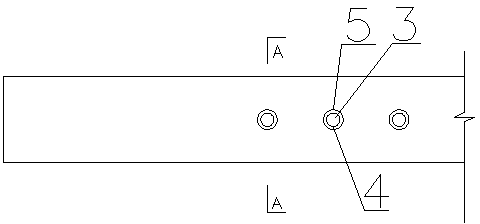
[0016] As shown in the figure, the steps of the present invention are as follows:

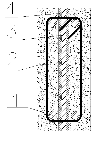
[0017] 1. Select fiber bars with a diameter of 10mm according to the length of the shear span of the concrete beam with longitudinal reinforcement 1 and stirrup 2 and the strength of the concrete.

[0018] 2. According to the calculation requirements of shear reinforcement design, drill corresponding holes 5 in the shear span area of ​​the beam and according to the width of the shear span area. The diameter of the hole 5 is 1.5 times the diameter of the fiber reinforcement, and the distance between adjacent holes 5 Equal to the spacing of the stirrups 3 in the shear span area, the position of the hole 5 is at the midpoint of the width of the beam cross section, that is, the middle of the cross section;

[0019] 3. Then pour epoxy resin glue 4 into the hole 5;

[0020] 4. Apply prestress to the selected fiber reinforcement 3, the applied prestress is 50% of its ultimate strength, and the method...

Embodiment 2

[0023] As shown in the figure, the steps of the present invention are as follows:

[0024] 1. According to the length of the shear span of the concrete beam with longitudinal reinforcement 1 and stirrup 2 and the strength of the concrete, select a fiber reinforcement with a diameter of 16mm.

[0025] 2. Drill corresponding holes 5 in the shear span area of ​​the beam according to the calculation requirements of the shear reinforcement design and according to the width of the shear span area. The diameter of the hole 5 is 1.8 times the diameter of the fiber reinforcement 3. The distance is equal to twice the distance between the stirrups 3 in the shear span area, and the hole 5 is located at the midpoint of the width of the beam cross section, that is, the middle of the cross section;

[0026] 3. Then pour epoxy resin glue 4 into the hole 5;

[0027] 4. Apply prestress to the selected fiber reinforcement 3, and the applied prestress is 70% of its ultimate strength. The method ...

Embodiment 3

[0030] As shown in the figure, the steps of the present invention are as follows:

[0031] 1. According to the length of the shear span of the concrete beam with longitudinal reinforcement 1 and stirrup 2 and the strength of the concrete, a fiber reinforcement with a diameter of 20mm is selected.

[0032] 2. Drill corresponding holes 5 in the shear span area of ​​the beam according to the calculation requirements of the shear reinforcement design and according to the width of the shear span area. The diameter of the hole 5 is 1.6 times the diameter of the fiber reinforcement 3. The distance is equal to 1.5 times the distance between the stirrups 3 in the shear span area, and the position of the hole 2 is at the midpoint of the width of the beam cross section, that is, the middle of the cross section;

[0033] 3. Then pour epoxy resin glue 4 into the hole 5;

[0034] 4. Apply prestress to the selected fiber reinforcement 3, and the applied prestress is 60% of its ultimate stre...


PUM


Abstract

The invention relates to a shear strengthening method of a concrete beam. The method comprises the following steps of: selecting a fiber reinforcement with a diameter of 8mm-25mm according to the shear span area length of the concrete beam and the strength of concrete; drilling corresponding holes in a shear span area of the beam, wherein the diameter of the holes is 1.5 to 1.5 times larger than the diameter of the fiber reinforcement, the distance between adjacent holes is 1 to 2 times larger than the distance between hoop reinforcements in the shear span area, and the holes are positioned in the midpoints of the cross beam of the beam in the width direction; filling epoxy resin glue in the holes; applying prestress on the selected fiber reinforcement; and inserting the fiber reinforcements with prestress into the holes to form a shear system formed by longitudinal reinforcements, the hoop reinforcements, the fiber reinforcements, and epoxy resin glue and the concrete. The method has the beneficial effects that the damage to a concrete protecting layer limited to the concrete beam itself is avoided, the middle of the beam is provided with the holes, and the fiber reinforcements are fully wrapped by epoxy resin and concrete, so that a greater anchoring force is generated, the material utilization rate is improved, and the debonding failure of the fiber reinforcements and the concrete is also prevented, and thus the utilization value of the fiber reinforcements is increased.

Description

technical field [0001] The invention relates to a method for shearing reinforcement of concrete beams in civil engineering and traffic engineering. Background technique [0002] For the shear reinforcement of concrete beams in civil and traffic engineering, the enlarged section method or surface bonding method (abbreviated as EB method) was first adopted, that is, post-cast concrete or adding steel plates, fiber cloth, etc. on the surface of concrete beams. The net height of the building is increased, and the weight of the structure is increased; the EB method is used for reinforcement. Since the reinforcement material is pasted on the surface of the concrete beam and exposed to the air, the durability is poor, and it will inevitably affect the human activity space in buildings with a large flow of people. , the material itself will also accelerate wear. In recent years, the embedding method [abbreviated as NSM method] has developed rapidly. However, this method needs to...

Claims


Application Information

Patent Timeline
Patent Type & Authority Applications(China)
IPC IPC(8): E04G23/02E01D22/00
Inventor 刘华新邢宪才刘蓓蓓王学志
Owner LIAONING UNIVERSITY OF TECHNOLOGY
Why Eureka
Try Eureka