
Multifunctional full-view three-dimensional adjustable microscopic visual device

A full-view, multi-purpose technology, applied in the field of material meso-mechanical behavior research, can solve the problems of complex device, simple structure, few observation functions, multiple devices, etc., to achieve low manufacturing and use costs, easy to master and use, easy to operate. Effect

Active Publication Date: 2013-12-18
ANHUI UNIV OF SCI & TECH
View PDF5 Cites 7 Cited by
  • Summary
  • Abstract
  • Description
  • Claims
  • Application Information

AI Technical Summary

Problems solved by technology

At present, some scholars have developed related devices and equipment. Cao Shugang et al. invented a three-dimensional mobile microscopic observation device (application number: CN200820099769.3) using a hierarchical microscopic bracket arrangement mode. Its disadvantage is that the device is relatively complicated and cumbersome, and It is impossible to ensure that the observation line of sight and the crack development of the specimen are in a vertical perspective; Zhou Cuiying and others invented a three-axis adjustable microscopic observation system for rock soil softening mesomechanics test (application number: CN200910036622.9), which also has the disadvantage of being unable to Realize the vertical viewing angle observation of the crack development of different test pieces, and the size that cannot be adjusted accurately in three dimensions
In summary, most of the visual devices are used for a certain type of test, and there are deficiencies such as unreasonable overall structure design, simple structure but few observation functions, and many functions but complex and bulky devices.

Method used


Image

  • Multifunctional full-view three-dimensional adjustable microscopic visual device

Examples


Embodiment Construction

[0019] The present invention will be further described below with reference to the drawings and embodiments.

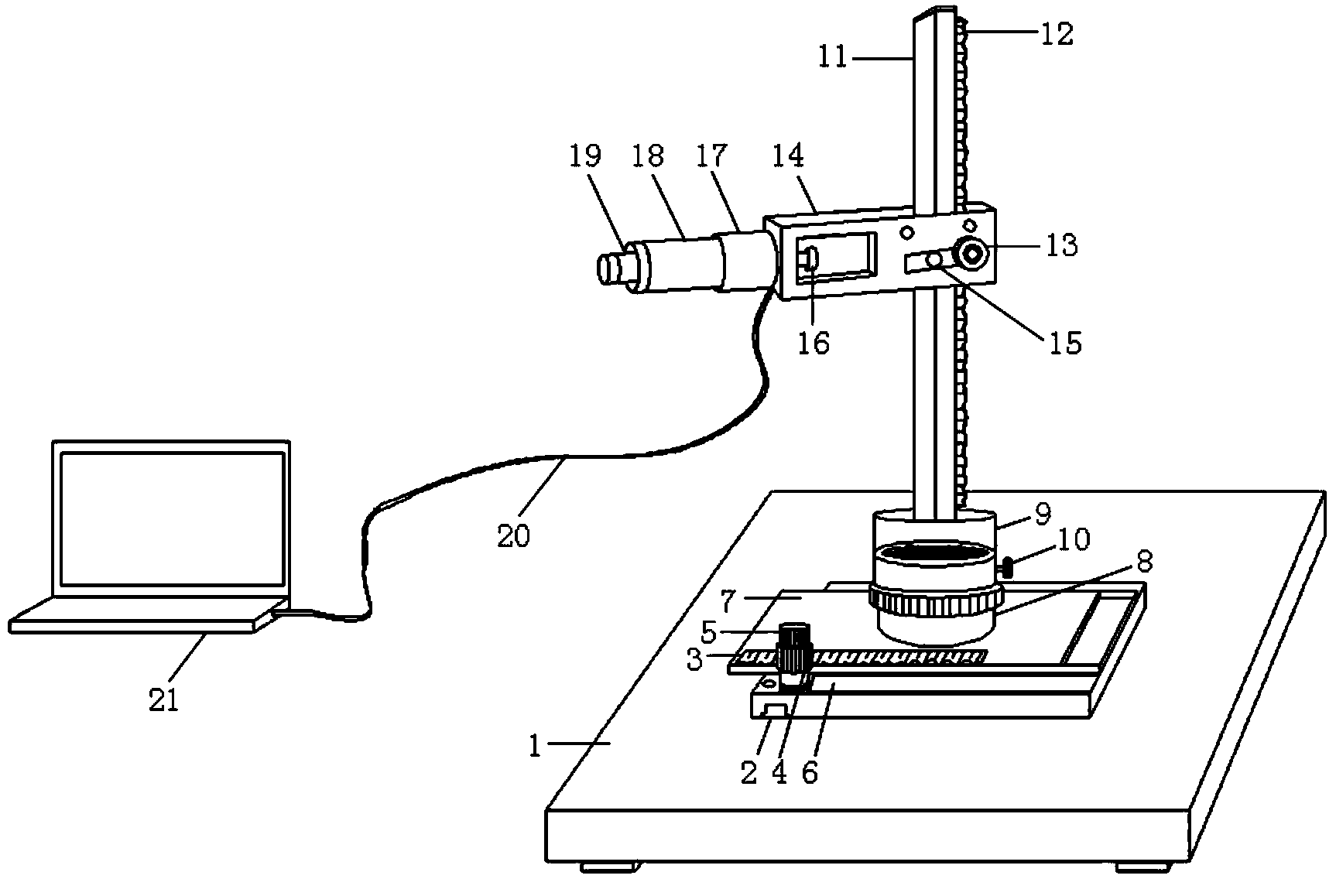
[0020] Such as figure 1 As shown, the present invention is a multi-purpose mesoscopic visualization device with full-view three-dimensional adjustment, which mainly includes a full-view three-dimensional adjustable system and a mesoscopic visualization system, and is supported by a base 1, an X-axis rack shaft 2 , Y-axis rack shaft 3, X-axis gear knob 4, Y-axis gear knob 5, X-axis slide plate 6, Y-axis slide plate 7, fixed disk seat 8, rotating bracket 9, pin bolt 10, Z-axis vertical rod 11, Z-axis rack shaft 12, Z-axis gear knob 13, frame 14, pin bolt 15, fixing bolt 16, FIT CCD camera 17, coaxial illumination light source 18, optical microscope 19, light source line and signal line 20, computer acquisition and analysis System 21 is composed.

[0021] Among them, the base support platform 1 has four bases, which are easy to manually place on the horizontal operation pla...


PUM


Abstract

The invention discloses a multifunctional full-view three-dimensional adjustable microscopic visual device which comprises a full-view three-dimensional adjustable system and a microscopic visual system, wherein the full-view three-dimensional adjustable system comprises a base supporting platform, an X-axis rack shaft, a Y-axis rack shaft, an X-axis gear knob, a Y-axis gear knob, an X-axis sliding plate, a Y-axis sliding plate, a fixed disc base, a rotary bracket, a locking bolt, a Z-axis vertical rod, a Z-axis rack shaft, a Z-axis gear knob, a frame and a locking bolt; the microscopic visual system comprises an FIT CCD (Frame Interline Transfer Charge Coupled Device) camera, a coaxial lighting source, an optical microscope, a fixed bolt, a light source line and a signal line, and a computer acquiring and analyzing system. The multifunctional full-view three-dimensional adjustable microscopic visual device has the main advantages of realizing full-view and three-dimensional accurate adjustability, being capable of dynamically observing, recording and analyzing microscopic mechanical behaviors of a material in a microscopic mechanical test in real time and full process, being simple in structure and convenient to operate, and providing an effective tool for researching the microscopic mechanical behaviors of multiple materials such as coal, rock and metal.

Description

Technical field [0001] The invention relates to the field of research on the meso-mechanical behavior of materials, in particular to a multi-purpose meso-visual device with full-view three-dimensional adjustable. Background technique [0002] With the continuous deepening of research work in various engineering fields, the exploration of the mechanical behavior of the research object has entered the mesoscopic stage. For example, coal and surrounding rock materials in the field of mining engineering are no longer only satisfied with the study of their macroscopic dynamic phenomena and mechanical behaviors, and the initiation, development, penetration, brittle fracture, or mesoscopic micro-cracks after being stressed. The mechanism and influencing factors of the nucleation, growth and confluence of microvoids, ductile fracture, and macroscopic cracks and fracture failure are the current research hotspots. Another example is the study of the mechanical properties of materials such...

Claims


Application Information

Patent Timeline
IPC IPC(8): G01N3/06
Inventor 李重情
Owner ANHUI UNIV OF SCI & TECH
Features
  • Generate Ideas
  • Intellectual Property
  • Life Sciences
  • Materials
  • Tech Scout
  • Unparalleled Data Quality
  • Higher Quality Content
  • 60% Fewer Hallucinations
Learn More