Method for judging fault type of winding based on power transformer
A technology for faults in power transformers and windings, which is applied in the measurement of electrical variables, instruments, and electrical measurement. It can solve the problems of inability to understand the internal deformation of the windings, affecting deployment, etc., to achieve convenient and fast implementation, simple operation, and accurate results. reliable results
- Summary
- Abstract
- Description
- Claims
- Application Information
AI Technical Summary
Problems solved by technology
Method used
Image
Examples
Embodiment 1
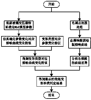
[0026] Such as figure 2 As shown, a method for judging a fault type based on a power transformer winding includes the following steps:
[0027] collecting frequency response data of the transformer under test, and drawing the frequency response data into a frequency response curve;
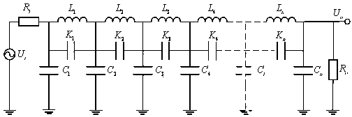
[0028] Establish and select various parameters of the KLC model according to the type of the transformer to be tested, simulate the KLC model, and obtain frequency response curve changes corresponding to different types of parameter changes by changing the parameters of the KLC model;
[0029] Establishing the deformation of the measured transformer winding and the corresponding relationship between the parameter changes of the KLC model;
[0030] Obtain the parameter change of the KLC model corresponding to the frequency response curve according to the frequency response curve of the transformer under test;
[0031] The deformation of the winding of the transformer under test is obtained accor...
Embodiment 2
[0038] Step (1): The preprocessing of the original data, the frequency response data can be collected directly by using most of the existing transformer winding frequency response testers on the market, and the obtained original data is a two-dimensional array corresponding to several sets of frequency and voltage ratios, Due to various electrical interference factors, there will be some glitch points with sudden changes in the voltage ratio, which need to be removed;
[0039] Step (2): According to a set of frequency response data obtained by processing, a frequency response curve corresponding to the winding phase can be drawn, and two frequency response curves can be obtained according to the two sets of frequency response data to be analyzed, and the two curves plotted on the same frequency response curve. For example, to analyze the state of the B-phase winding of the transformer, you can analyze the AB and BC phase windings or the OA and OB phase windings, so the frequen...
Embodiment 3
[0046] The frequency response signal collected by the transformer winding frequency response tester is preprocessed to obtain the frequency response curves of the medium-voltage side BC and CA phases, and draw them in the same frequency response curve diagram, as shown in Figure 5 shown;
[0047] The simulation of the winding model established according to the suggested parameters can be obtained. The corresponding relationship between the change of the model parameters and the corresponding characteristics of the change of the frequency response curve is shown in the following brief table
[0048]
[0049]
[0050] right Figure 5 The analysis of the characteristics of the frequency response curves of the BC and CA phases on the medium voltage side shows that some peaks and valleys of the frequency response curve in the 300kHz-500kHz frequency band are shifted, and the value of some valleys is significantly reduced, and several valleys are added. In addition, the trou...
PUM
 Abstract
Description
Claims
Application Information
 - R&D
- Intellectual Property
- Life Sciences
- Materials
- Tech Scout
- Unparalleled Data Quality
- Higher Quality Content
- 60% Fewer Hallucinations
Browse by: Latest US Patents, China's latest patents, Technical Efficacy Thesaurus, Application Domain, Technology Topic, Popular Technical Reports.
© 2025 PatSnap. All rights reserved.Legal|Privacy policy|Modern Slavery Act Transparency Statement|Sitemap|About US| Contact US: help@patsnap.com


