
Current transformer polarity tester

A technology of current transformer and tester, which is applied in the field of electric power equipment, can solve the problems of polarity correctness judgment, polarity test difficulty, and many test instruments, so as to improve accuracy, improve work test efficiency, and solve capacity shortage Effect

Active Publication Date: 2013-12-18
GUANGDONG WEIHENG POWER TRANSMISSION & DISTRIBUTION ENG +1
View PDF5 Cites 16 Cited by
  • Summary
  • Abstract
  • Description
  • Claims
  • Application Information

AI Technical Summary

Problems solved by technology

However, the 380V short-circuit test method requires many test instruments, complicated wiring, and certain safety risks. At the same time, due to the limitation of the test voltage, the current measured on the secondary side is very small, and it is difficult to judge the correctness of the polarity.
[0006] Therefore, in order to solve the above-mentioned problem that the polarity test of the transformer bushing current transformer is difficult after installation, it is necessary to provide a current transformer polarity test with high polarity test accuracy, high test efficiency, portability and convenient use. instrument to improve the reliability of transformer operation and ensure the safe and stable operation of the power system

Method used


Image

  • Current transformer polarity tester
  • Current transformer polarity tester

Examples


Embodiment

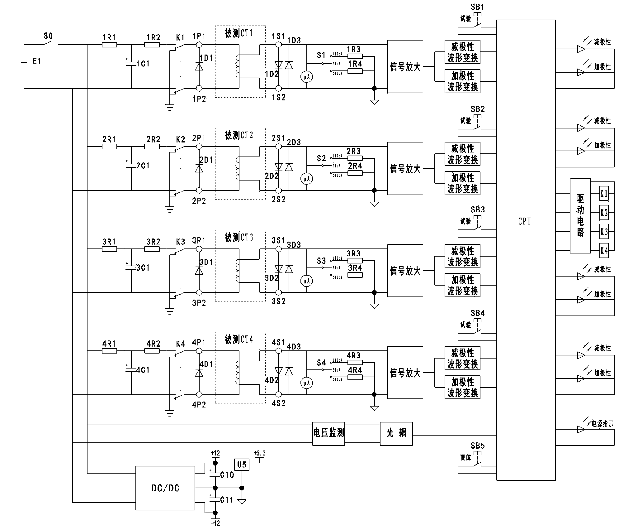
[0041] This embodiment takes the current transformer polarity tester as a four-channel current transformer polarity tester as an example to describe the following.

[0042] The circuit diagram of the current transformer polarity tester of the present invention is as figure 1 As shown, it includes a power circuit for supplying power; four sets of primary loops electrically connected to the primary coil of the current transformer; four sets of secondary loops electrically connected to the secondary coil of the current transformer; and for collecting and processing information, And display the test results of the CPU circuit; wherein, the power circuit is electrically connected to each group of primary circuits, each group of secondary circuits and the CPU circuit; each group of secondary circuits is respectively connected to the CPU circuit signal.

[0043] The power circuit includes a 12V rechargeable lithium-ion battery as a power source, a power switch S0, a DC / DC isolation m...


PUM


Abstract

The invention provides a current transformer polarity tester. The tester comprises a power circuit for supplying power, at least one group of primary return circuits electrically connected with a primary coil of a current transformer, at least one group of secondary return circuits electrically connected with a secondary coil of the current transformer and a CPU circuit used for collecting and processing information and displaying a test result. The power circuit is respectively and electrically connected with each group of primary return circuits, each group of secondary return circuits and the CPU circuit, each group of secondary return circuits are respectively in signal connection with the CPU circuit, and the number of the primary return circuit is the same as that of the secondary return circuits. The tester is high in test accuracy and test efficiency, convenient to carry and convenient and rapid to use. Lithium batteries are adopted in the tester for power supply, and meanwhile the tester can test the polarity of at least more than one group of transformer bushing current transformers. Compared with a traditional tester, the tester shortens polarity test time greatly, and therefore the work test efficiency is improved and popularization of the tester is facilitated.

Description

technical field [0001] The invention relates to the technical field of electric equipment, and more specifically relates to a current transformer polarity tester. Background technique [0002] Current transformer is an important part of power system, it is widely used in relay protection, electric energy metering, remote measurement and control, system fault filtering and so on. In the construction of power system infrastructure or technical upgrading projects, it is very necessary to conduct polarity tests before and after the handover and overhaul of current transformers, because the primary and secondary sides of current transformers have two or more lead-out terminals. The wrong use of the lead-out terminals on the secondary side will cause the phase of the secondary side to change by 180 degrees, which will not only affect the correct operation of the relay protection device, but also affect the operation monitoring and accident handling of the power system. In severe c...

Claims


Application Information

Patent Timeline
IPC IPC(8): G01R31/06
Inventor 廖志鹏梁如平陈慕霞朱翠媚李建锋
Owner GUANGDONG WEIHENG POWER TRANSMISSION & DISTRIBUTION ENG
Learn More