Wireless temperature control system

A control system and wireless temperature technology, applied in the field of thermometers, can solve the problems of difficulty in implementation, complicated use, waste of labor, etc., and achieve the effect of improving the accuracy of temperature detection and saving manpower and costs

Active Publication Date: 2013-12-18
CHONGQING JINLONG TECH
View PDF6 Cites 11 Cited by
  • Summary
  • Abstract
  • Description
  • Claims
  • Application Information

AI Technical Summary

Problems solved by technology

[0002] With the development of national economic construction, there is an urgent need to realize the automatic management of these places, such as grain storage warehouses, civilian vegetable greenhouses, and civilian breeding bases. To realize automatic management, it is necessary to monitor the temperature automatically at multiple points. At present, many places are due to Difficult to do for technical and cost reasons
Although multi-point detection is also used for civilian use, including greenhouses and breeding bases, they all use manual monitoring of multiple points one by one, and record one by one, so that it is impossible to monitor multiple monitoring points at the same time from time to time. It is an alcohol thermometer, which has a certain delay time for the change of ambient temperature, which not only wastes manpower, time and effort, but also the effect is not good, because someone needs to enter the specific site to observe and record, so that one entry and one exit will affect the entire ecological environment. It has a great impact, which is not conducive to the growth of plants, and such management cannot realize the overall automatic control, and a high-yield scientific management cannot be realized. The existing automatic temperature monitoring system is too expensive and complicated to use. Farmers cannot accept and operate; in addition, although multi-point temperature monitoring is currently used for national grain storage, most of them use wired monitoring, and the monitoring equipment is complicated. Once the line is damaged, the monitoring will fail, and the use of wired will cause circuit damage after a long time. This will not only increase the cost but also cause a short circuit and cause a fire.

Method used


Image

  • Wireless temperature control system
  • Wireless temperature control system
  • Wireless temperature control system

Examples


Embodiment Construction

[0073] In order to make the object, technical solution and advantages of the present invention clearer, the implementation manner of the present invention will be further described in detail below in conjunction with the accompanying drawings.

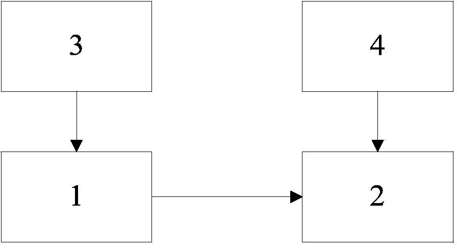
[0074] In order to improve the accuracy of temperature control and reduce production costs, the embodiment of the present invention provides a wireless temperature control system, see figure 1 , see the following description for details: The wireless temperature control system includes: a transmitter control circuit 1, a receiver control circuit 2, a first power supply circuit 3 and a second power supply circuit 4, the first power supply circuit 3 provides 9V and 5V power supplies, and the second The power circuit 4 provides 3.3V power.

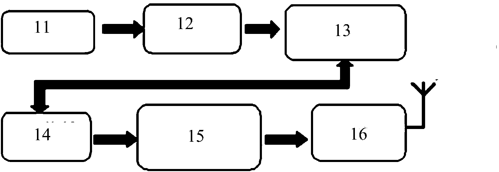
[0075] Among them, see figure 2 The transmitter control circuit 1 includes: a temperature sensing circuit 11, an electrical signal amplification circuit 12, a voltage frequency conversion circuit 13...


PUM


Abstract

The invention discloses a wireless temperature control system, and relates to the field of temperature detection. The wireless temperature control system collects temperature in a granary and other places through a receiving end and a transmitting end, realizes accurate collection of the temperature through an electric signal amplification circuit, a digital signal amplitude modulator circuit, a transmission tuning circuit, a first CPU control unit, a second CPU control unit and the like, and also can display the detected temperature in real time through a digital display tube. When a user finds that the detected temperature is not within a standard working range, the user can regulate the temperature of the granary and the other places in time so as to avoid over-wet or over-dry or other conditions. The wireless temperature control system improves temperature detection accuracy, saves manpower, reduces cost, and meets various requirements in practical application.

Description

technical field [0001] The invention relates to a thermometer, in particular to a wireless temperature control system. Background technique [0002] With the development of national economic construction, there is an urgent need to realize the automatic management of these places, such as grain storage warehouses, civilian vegetable greenhouses, and civilian breeding bases. To realize automatic management, it is necessary to monitor the temperature automatically at multiple points. At present, many places are due to Difficult to do for technical and cost reasons. Although multi-point detection is also used for civilian use, including greenhouses and breeding bases, they all use manual monitoring of multiple points one by one, and record one by one, so that it is impossible to monitor multiple monitoring points at the same time from time to time. It is an alcohol thermometer, which has a certain delay time for the change of ambient temperature, which not only wastes manpower...

Claims


Application Information

Patent Timeline
Patent Type & Authority Applications(China)
IPC IPC(8): G05D23/19
CPCG01K1/024G01K1/026
Inventor 范长和
Owner CHONGQING JINLONG TECH
Why Eureka
Try Eureka