
Split type radio frequency coaxial adaptor

A radio frequency coaxial and adapter technology, applied in the direction of connection, contact parts, two-part connection device, etc., can solve the problem that the radio frequency cable adapter cannot meet the actual use requirements, it is difficult to prove the reliability of the radio frequency cable Insufficient connection reliability and coaxiality, etc., to achieve the effect of improving connection reliability and coaxiality, good electrical performance, and reducing production costs

Active Publication Date: 2013-12-18
CAC ELECTRONICS TECH
View PDF6 Cites 8 Cited by
  • Summary
  • Abstract
  • Description
  • Claims
  • Application Information

AI Technical Summary

Problems solved by technology

[0003] In the 1.85mm RF coaxial adapter in the prior art, the inner conductor is usually a one-piece structure. Although it is easy to process, the electrical performance is insufficient; the material selection of the outer conductor also needs to be improved, and it is usually difficult to achieve low Dielectric constant, choosing a material with a low dielectric constant is difficult to prove the connection reliability of the RF cable adapter. For the outer conductor material that takes both connection reliability and electrical performance into account, the cost of the RF cable adapter will be higher. The cost performance is difficult to meet the market demand
In addition, the connection reliability and coaxiality of the existing RF cable adapters are still insufficient, which makes the RF cable adapters unable to meet the actual use requirements

Method used


Image

  • Split type radio frequency coaxial adaptor

Examples


Embodiment Construction

[0016] The content of the present invention will be described below in conjunction with specific embodiments.

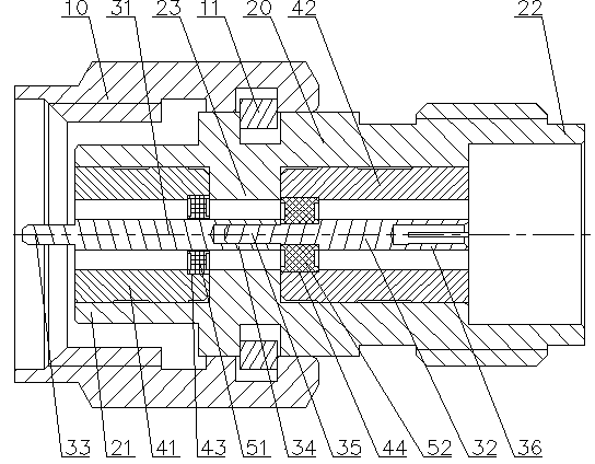
[0017] Such as figure 1 As shown in FIG. 2 , it is a structural schematic diagram of the split-type radio frequency coaxial adapter according to the present invention. This embodiment provides a specific split-type RF coaxial adapter, that is, a split-type 1.85mm RF coaxial adapter, including: a nut 10, an outer shell 20, an outer conductor, an inner conductor, and a dielectric body. The outer shell The body 20 includes a plug end 21 and a socket end 22, the outer conductor is arranged in the outer casing 20 and is interference fit with the outer casing 20, the inner conductor is arranged in the outer conductor, and the nut 10 Set at the plug end 21 of the outer shell 20, the dielectric body is set in the outer conductor and has an interference fit with the outer conductor, and the inner conductor is set in the dielectric body and interferes with the dielectric body...


PUM


Abstract

The invention discloses a split type radio frequency coaxial adaptor which comprises a nut, a casing body, an outer conductor and inner conductors. The casing body comprises an insertion head end and an insertion base end, the outer conductor is arranged in the casing body and is in interference fit with the casing body, the inner conductors are arranged in the outer conductor, and the nut is arranged at the insertion head end of the casing body. The inner conductor comprises a first inner conductor and a second inner conductor, the two ends of the first inner conductor are provided with a first insertion pin and a first insertion hole respectively, the two ends of the second inner conductor are provided with a second insertion pin and a second insertion hole respectively, the first insertion pin is located at the insertion head end of the casing body, the second insertion pin is located in the first insertion hole, and the second insertion hole is located in the insertion base end of the casing body. The processing technology of a radio frequency electric cable adaptor is simplified, production efficiency is improved, production cost is reduced, particularly, such as a split type 1.85mm radio frequency coaxial adaptor, and the voltage standing wave ratio of the adaptor is smaller than or equal to 1.45 under DC-65GHz.

Description

technical field [0001] The invention relates to a split-type radio frequency coaxial adapter, which belongs to the technical field of electrical connectors. Background technique [0002] The 1.85mm connector adapter can work up to 65GHz, with a wide operating frequency and small size. It can be applied to microwave and millimeter wave coaxial signal transmission. Because it works in the millimeter wave band, it is extremely difficult to design and process. In China, 1.85mm connection The adapter is still in the trial stage, and the highly reliable 1.85mm adapter is blank. [0003] In the 1.85mm RF coaxial adapter in the prior art, the inner conductor is usually a one-piece structure, although it is easy to process, but the electrical performance is insufficient; the material selection of the outer conductor also needs to be improved, and it is usually difficult to achieve low Dielectric constant, choosing a material with a low dielectric constant is difficult to prove the c...

Claims


Application Information

Patent Timeline
IPC IPC(8): H01R13/02H01R13/03H01R13/40H01R13/516H01R24/54
Inventor 胡汝刚
Owner CAC ELECTRONICS TECH
Learn More