Method and integrated system for removing target gas component in source gas

A technology of gas composition and source gas, which is applied in separation methods, chemical instruments and methods, dispersed particle separation, etc., and can solve problems such as low energy utilization rate and operating cost to be improved

Active Publication Date: 2013-12-25
青岛海山减碳环保科技有限公司
View PDF0 Cites 24 Cited by
  • Summary
  • Abstract
  • Description
  • Claims
  • Application Information

AI Technical Summary

Problems solved by technology

[0011] The present invention aims to solve the existing post-combustion CO capture 2 The technical problems of materials, low energy utilization, safety, and operating costs need to be improved, and provide a carbon dioxide capture whole-process integrated system and a method of using the system to capture carbon dioxide

Method used


Image

  • Method and integrated system for removing target gas component in source gas
  • Method and integrated system for removing target gas component in source gas
  • Method and integrated system for removing target gas component in source gas

Examples


Embodiment 1

[0079] Example 1 (rich liquid split type)

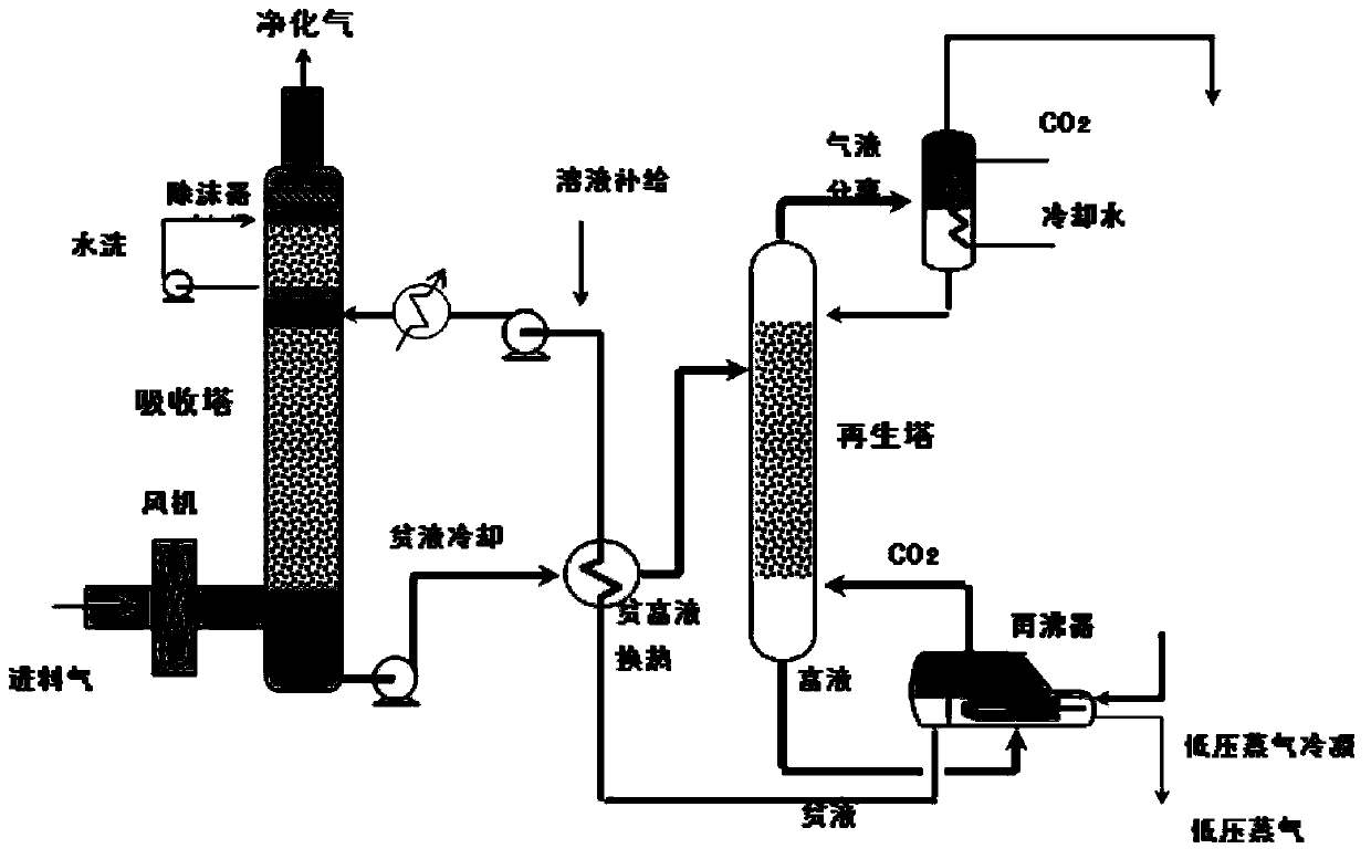
[0080] Refer below image 3 To illustrate the use of the optimized CO of the present invention 2 capture process system for CO 2 Capture process steps. The capture process can be applied to the CO in the flue gas emitted by the combustion of thermal power plants 2 catch. The temperature of the raw gas from the flue gas is 50°C, the pressure of the raw gas is 0.03MPa, and the composition of the raw gas is: CO 2 is 51.95v / v%, H 2 is 19.74v / v%, CO is 9.71v / v%, CH 4 is 16.09v / v%, H 2 O is 0.87v / v%, N 2 It is 1.64v / v%, all in volume percentage. The flue gas flow rate entering the absorption tower is 5000Nm 3 / h.

[0081] Under the action of the fan, the raw material gas (also known as flue gas) is dehydrated and cooled (at a temperature of 35°C) and enters the absorption tower C101 from above the liquid level of the liquid storage tank of the absorption tower, and flows from bottom to top. The absorption liquid is supplied fro...

Embodiment 2

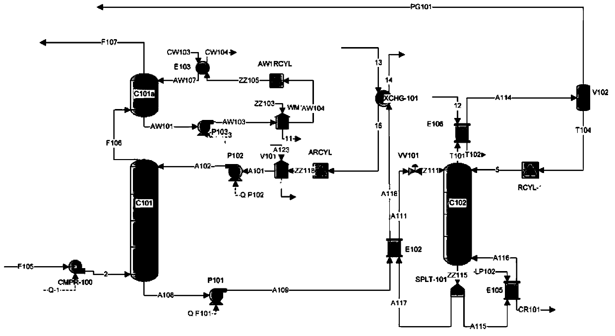
[0088] Example 2 (rich liquid multi-stage heat exchange type)

[0089] Refer below Figure 4 To illustrate the use of the liquid-rich multistage heat exchange type CO of the present invention 2 capture process system for CO 2 Capture process steps. exist Figure 4 In this process, the rich liquid flowing out from the bottom of the absorption tower C101 is first heated to a certain temperature by the first-stage lean-rich liquid heat exchanger E102, and the heated rich liquid is regenerated by the CO discharged from the top of the tower through the second-stage heat exchanger E106. 2 The gas is heated, and the rich liquid continues to be heated by the lean liquid flowing out from the bottom of the regeneration tower through the third-stage heat exchanger XCHG-102, and finally flows in from the top of the regeneration tower. This process not only fully preheats the rich liquid and saves the amount of regeneration steam, but also cools the lean liquid, further saving the cool...

Embodiment 3

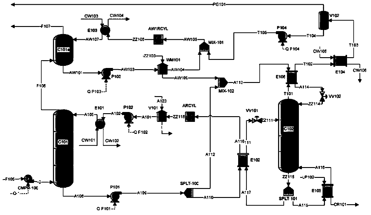
[0097] Embodiment 3 (cross heat exchange type)

[0098] Refer below Figure 5 To illustrate the use of cross-exchange heat CO of the present invention 2 capture process system for CO 2 Capture process steps. exist Figure 5 In the process, the rich liquid flowing out from the bottom of the absorption tower is firstly heat-exchanged by the first-stage lean-rich liquid and then split, part of it flows through the second-stage lean-rich liquid heat exchanger to exchange heat with the high-temperature lean liquid, and the rest passes through the heat exchanger and the regeneration The overhead product gas is subjected to heat exchange.

[0099] The specific process is as follows:

[0100] Using the flue gas with the same composition as in Example 1 (the temperature and pressure are also the same as in Example 1), under the action of the fan, the above-mentioned raw material gas is dehydrated and cooled (at a temperature of 35°C) from above the liquid level of the absorption t...


PUM


Abstract

The invention provides a method for removing a target gas component in source gas. The method comprises the following steps: a) allowing source gas containing the target gas component to pass through an absorption tower, carrying out gas absorption in the absorption tower and allowing absorbed poor gas to enter into a water scrubber; b) cyclically using cyclic excess water in the water scrubber; c) subjecting a rich liquid from the bottom of the absorption tower to heat exchange with a poor liquid flowing out from the bottom of a regeneration tower in a poor-rich liquid heat exchanger and then allowing the rich liquid to enter into the top of the regeneration tower; d) stripping the rich liquid with rising steam and allowing obtained poor liquid to flow out from the bottom of the regeneration tower and to be delivered to the absorption tower; e) allowing a stripped steam mixture containing target gas to depart from the top of the regeneration tower, condensing steam in a gas-liquid separator and allowing the target gas to depart from the gas-liquid separator and to be transferred to a storage part; and f) introducing a condensate of the gas-liquid separator into the top of the absorption tower and the water scrubber again. The invention further provides an integrated system for removing the target gas component in the source gas.

Description

technical field [0001] The present application relates to a method and integrated system for removing a target gas component from a source gas. More particularly, it relates to a method and apparatus for removing and capturing carbon dioxide from power plant exhaust. Background technique [0002] The increasing presence of carbon dioxide in the atmosphere, a greenhouse gas, is believed to have directly contributed to global climate change. The carbon dioxide produced by the burning of fossil fuels to generate electricity is the main cause of the increase in the concentration of carbon dioxide in the atmosphere. Currently more than 85% of the world's energy demand comes from fossil fuels because of its reliable energy production technology, low cost, strong applicability and high energy density. [0003] It is reported that the consumption of fossil fuels will increase by 27% in the next 20 years. Therefore, one of the main efforts of the international community to deal wi...

Claims


Application Information

Patent Timeline
Patent Type & Authority Applications(China)
IPC IPC(8): B01D53/14B01D53/18
Inventor 王宝冬孙琦
Owner 青岛海山减碳环保科技有限公司
Why Eureka
Try Eureka