Multifunctional numerical control gear grinding machine tool

A multi-functional, gear-grinding technology, which is applied in the direction of grinding machine parts, gear cutting machines, gear teeth, etc., can solve the problems of inconvenient detection, inability to perform strong grinding, and inability to forcefully grind products with special-shaped contours, etc., to achieve Save adjustment time, the effect is obvious

Active Publication Date: 2013-12-25
常州紫云英机电工程有限公司
View PDF9 Cites 12 Cited by
  • Summary
  • Abstract
  • Description
  • Claims
  • Application Information

AI Technical Summary

Problems solved by technology

As far as the current domestic rack processing is concerned, it is largely processed by ordinary machine tools, and it is difficult to guarantee the accuracy and quality.
[0006] At present, the number of CNC form grinding machine tools developed in China is relatively small, and the price is expensive.
There used to be a tooth-shaped grinding machine converted from a gantry guide rail grinding machine in China. Its disadvantages are that it is inconvenient to clamp the workpiece and inconvenient to detect.
Every time the helical rack is ground, special tooling must be made to ensure the helix angle and affect the accuracy
Since the grinding head is suspended on the ram for up and down movement, the rigidity is affected and it cannot be used for strong grinding
[0007] As for the broach grinding machine produced in China, it is a light-duty grinding machine, not a strictly defined gear grinding machine, and its efficiency is very slow. It is not suitable for large-scale grinding of racks, nor can it be used for powerful grinding of products with various special-shaped contours.

Method used


Image

  • Multifunctional numerical control gear grinding machine tool
  • Multifunctional numerical control gear grinding machine tool
  • Multifunctional numerical control gear grinding machine tool

Examples


Embodiment Construction

[0030] The present invention will now be described in further detail with reference to the drawings. These drawings are all simplified schematic diagrams, which merely illustrate the basic structure of the present invention in a schematic manner, so they only show the structures related to the present invention.

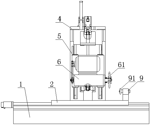
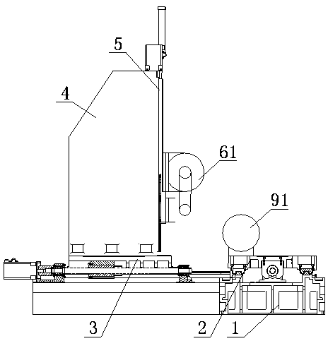
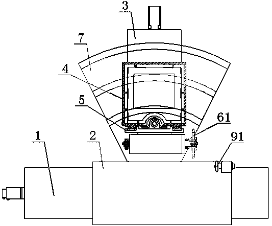
[0031] Such as Figure 1~3 As shown, the first embodiment of a multifunctional numerical control gear grinding machine tool of the present invention includes a bed 1 and a numerical control system that controls the operation of the devices. The bed 1 is provided with a longitudinal sliding table 2 and a lateral sliding table 3, A column 4 is installed on the sliding table 3, a vertical sliding table 5 is installed on the column 4, and a grinding head assembly 6 is installed on the vertical sliding table 5.

[0032] A longitudinal sliding mechanism is provided between the longitudinal sliding table 2 and the bed 1, and the longitudinal sliding mechanism includes a longitu...


PUM


Abstract

The invention relates to a multifunctional numerical control gear grinding machine tool, which comprise a machine tool body and a numerical control system for controlling devices to work, wherein the machine tool body is provided with a longitudinal sliding table and a transverse sliding table; a vertical column is arranged on the transverse sliding table; a vertical sliding table is arranged on the vertical column; a grinding head assembly is arranged on the vertical sliding table; a longitudinal sliding mechanism is arranged between the longitudinal sliding table and the machine tool body; a transverse sliding mechanism is arranged between the transverse sliding table and the machine tool body; a vertical sliding mechanism is arranged between the vertical sliding table and the vertical column; and the grinding head assembly comprises a grinding wheel grinding head and a motor for driving the grinding wheel grinding head to rotate. According to the multifunctional numerical control gear grinding machine tool, full numerical control is adopted, a computer numerical control (CNC) system is used for controlling the work of each working component, so that integration of auxiliary technologies such as profile grinding, online trimming, an online real-time measurement technology and an automatic machining allowance allocation technology is realized, and the adjusting time of profile grinding can be saved.

Description

Technical field [0001] The invention relates to the technical field of gear grinding equipment, in particular to a multifunctional numerically controlled gear grinding machine tool, which can not only perform powerful single-tooth or multi-tooth forming grinding on straight racks and helical racks, but also suitable for precision broaching, internal and external Gears, worm gears, worms, splines, compressor rotors, engine connecting rods, bearing covers and other products are shaped and ground. Background technique [0002] Gear and rack transmission is an important form of transmission in mechanical transmission. Compared with other forms of mechanical transmission, gear and rack transmission are reliable, longer life, stable transmission ratio, high transmission efficiency, and suitable for a wide range of power and speed. Therefore, rack transmission is widely used in aircraft, automobiles, and precision instruments. , Metallurgy, mining, shipbuilding and power generation ind...

Claims


Application Information

Patent Timeline
Patent Type & Authority Applications(China)
IPC IPC(8): B23F1/02B23F23/00B23Q1/25B23Q5/40B23Q16/02B24B53/075
Inventor 陈强
Owner 常州紫云英机电工程有限公司
Why Eureka
Try Eureka