
Cement lining device of centrifugal spherical graphite cast-iron pipe

A centrifugal ductile iron and cement technology, applied in ceramic molding machines, manufacturing tools, etc., can solve problems such as uneven rotation speed of driving rollers, waste pipes, blockage of hydraulic valves, etc., to improve product quality, production efficiency, and rotational speed. Uniform and stable effect

Active Publication Date: 2013-12-25
XINXING DUCTILE IRON PIPES CO LTD
View PDF6 Cites 12 Cited by
  • Summary
  • Abstract
  • Description
  • Claims
  • Application Information

AI Technical Summary

Problems solved by technology

Due to the dirty environment during the lining of the cement layer, the main impurity is cement dust, which often causes the hydraulic system to enter the cement, causing the hydraulic valve to be blocked, so that the hydraulic motor cannot work normally, which seriously affects the production efficiency
In addition, if two drive motors are used to drive the same ductile iron pipe, due to the bending of the ductile iron pipe, it is difficult to ensure that the two motors drive the ductile iron pipe to rotate at the same time, which often results in uneven rotation speed of the driving roller, which makes the rotation of the ductile iron pipe If the speed is not enough, the lining cement of the pipe will not be compacted, and the cement layer will be uneven, resulting in waste pipes

Method used


Image

  • Cement lining device of centrifugal spherical graphite cast-iron pipe
  • Cement lining device of centrifugal spherical graphite cast-iron pipe
  • Cement lining device of centrifugal spherical graphite cast-iron pipe

Examples


Embodiment 1

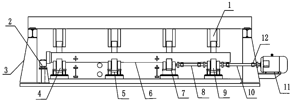
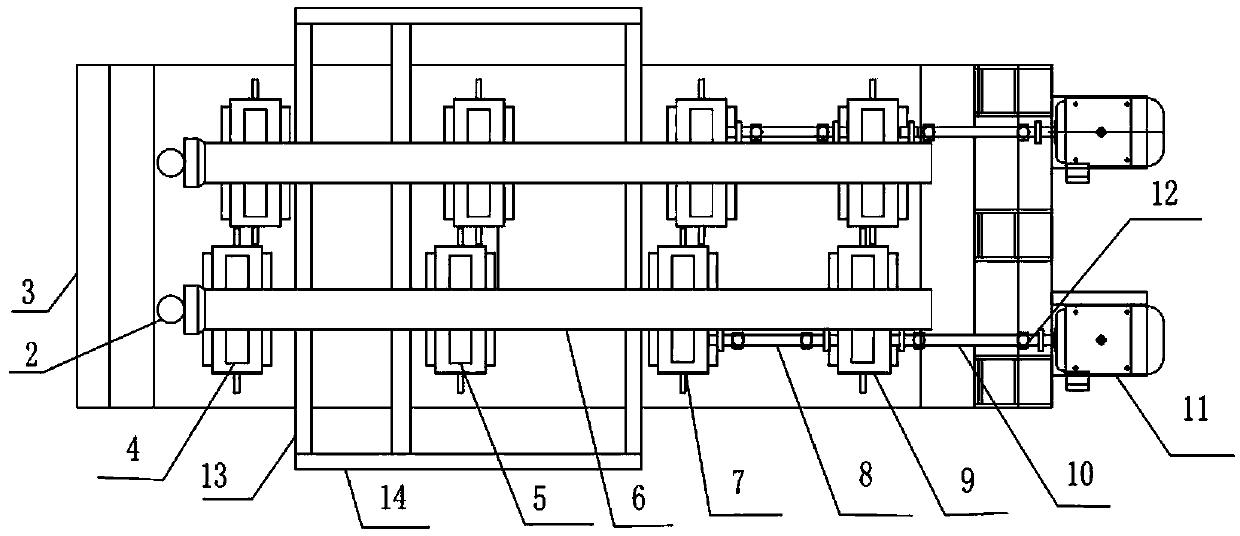
[0016] Depend on Figure 1 to Figure 3 It can be seen that the present invention mainly includes a frame 3, a pressure roller group 1, a first driving roller group 7, a second driving roller group 9, a first driven roller group 4, a second driven wheel roller group 5 and a block Wheel 2, the first driving idler set 7, the second driving idler set 9, the first driven idler set 4, and the second driven idler set 5 are all installed on the frame 3, and on the Above the corresponding positions of the first driving idler set 7, the second driving idler set 9, the first driven idler set 4, and the second driven idler idler set 5, a pinch roller set 1 is installed, and the pinch roller set 1 is fixed on the frame 3, and each pressure roller group 1 is controlled by a hydraulic cylinder to lift up and down, and the retaining wheel 2 is installed on the frame 3 on the side of the first driven supporting roller group 4, and the axis of the retaining wheel 2 and the nodular cast iron Th...

Embodiment 2

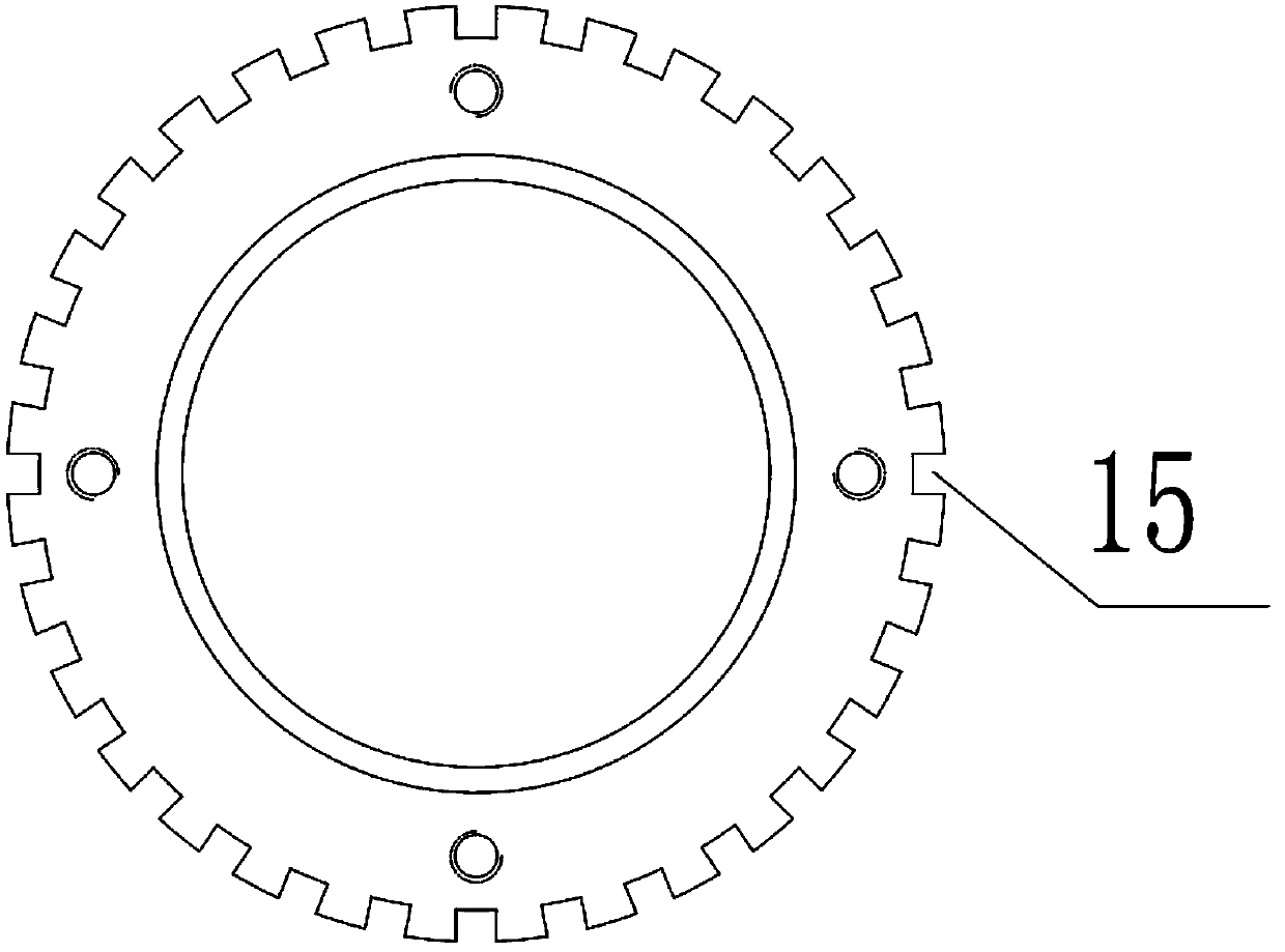
[0024] Depend on Figure 4 It can be seen that in the present invention, the section of the elongated groove 15 in the retaining wheel 2 is trapezoidal, and the effect described in the first embodiment can also be achieved.


PUM


Abstract

The invention discloses a cement lining device of a centrifugal spherical graphite cast-iron pipe, and relates to the technical field of cement lining of the spherical graphite cast-iron pipe. The cement lining device mainly comprises a frame, a pressing wheel set, a first drive riding wheel set, a second drive riding wheel set, a first driven riding wheel set, a second driven riding wheel set, and a baffle wheel. A drive motor is mounted on one side of the second drive riding wheel set of the frame, the drive riding wheels of the second drive riding wheel set is connected with the drive motor through a second transmission shaft, and the drive riding wheels of the first drive riding wheel set is connected with the drive riding wheels of the second drive riding wheel set through a first transmission shaft. Elongated grooves are uniformly and axially distributed on an outer periphery face on which the baffle wheel is in contact with a spherical graphite cast-iron pipe end. By the aid of the cement lining device, uniformity and stability of rotation speed of the spherical graphite cast-iron pipe can be guaranteed, a uniform and tight cement layer is formed on the inner wall of the spherical graphite cast-iron pipe, quality of cement lining of the spherical graphite cast-iron pipe is effectively improved, and production efficiency is improved.

Description

technical field [0001] The invention relates to the technical field of cement lining of ductile iron pipes. Background technique [0002] At present, after the water pressure is applied to the ductile iron pipe at home and abroad, the inner wall of the pipe must be coated with a cement layer to play a role in anti-corrosion (to prevent water and other media from directly contacting the interior of the ductile iron pipe). Inside the pipe, the pipe is rotated at high speed, and the centrifugal force generated by the rotation is used to compact the cement and adhere to the inner wall of the ductile cast iron pipe. The equipment at home and abroad generally uses 8 sets of support rollers and 4 sets of pressure rollers to fix the pipe for each ductile cast iron pipe. The wheel is placed at the bottom to drag the ductile iron pipe, and a pressure wheel presses the pipe on the support roller. There are 4 positions for a pipe to support. The traditional driving support roller is se...

Claims


Application Information

Patent Timeline
IPC IPC(8): B28B1/34
Inventor 闫海峰王佩合武东起张云波
Owner XINXING DUCTILE IRON PIPES CO LTD
Learn More