Composite type solid-waste gasifying device

A solid waste and gasification device technology, applied in the direction of granular/powdered fuel gasification, etc., can solve the problems of lack of large-scale commercial application, high carbon content in flue gas tar and bottom slag, and achieve rapid gasification low carbon content in ash and slag, and low emissions

Inactive Publication Date: 2013-12-25
ZHEJIANG UNIV
View PDF3 Cites 10 Cited by
  • Summary
  • Abstract
  • Description
  • Claims
  • Application Information

AI Technical Summary

Problems solved by technology

In addition, existing solid waste gasification devices generally have the disadvantage of high carbon content in flue gas tar and bottom residue
However, the solid waste gasification devices reported in other literatures and patents are generally small-scale laboratory test devices, lacking the possibility of large-scale commercial application

Method used


Image

  • Composite type solid-waste gasifying device

Examples


Embodiment Construction

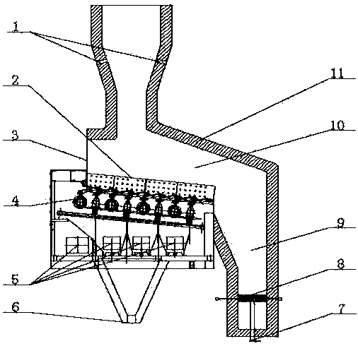
[0009] Such as figure 1 As shown, the composite solid waste gasification device of the present invention includes: a reciprocating fire grate 2 , a fluidized bed 9 and a rear arch 11 . The reciprocating fire grate 2 is fixed on the side wall of the fluidized bed 9 , and the rear arch 11 is fixed on the top of the fluidized bed 9 . The reciprocating grate 2 is composed of movable grate pieces and fixed grate pieces arranged in a staggered manner. There are several high-temperature primary tuyeres 5 under the reciprocating grate 2. The bottom slag collection device 6 is fixed at the bottom of the reciprocating grate 2. . The lower part of the fluidized bed 9 is provided with a fluidized bed air distribution plate 8 , and the center of the fluidized bed air distribution plate 8 is provided with a slag discharge pipe 7 . Two tertiary air outlets 1 are symmetrically opened on the same horizontal plane at the top of the back arch 11 .

[0010] The working process of the present i...


PUM


Abstract

The invention discloses a composite type solid-waste gasifying device. The composite type solid-waste gasifying device is characterized in that a reciprocating grate and a bubbling fluidized-bed reactor structure are combined, waste is firstly dried, pyrolyzed and gasified on the front-section reciprocating grate, and the rear-section fluidized bed device is used for pyrolysis of residual waste and suspended combustion of gasified slag. The reciprocating grate adopts a plurality of sections of high-temperature air distribution to dry, pyrolyze and gasify the waste so as to provide partial heat, and a long rear arch maintains high temperature under high-temperature flue gas, and is used for increasing radiant heat on the grate and providing energy for pyrolyzing and gasifying the waste with low calorific value. The high-temperature flue gas generated by combustion of a fluidized bed maintains high-temperature environment of the wall surface of the rear arch of the grate, and the slag is discharged by a slag discharging hole at the middle part of an air distributing plate of the fluidized bed. The composite type solid-waste gasifying device disclosed by the invention has the beneficial effects that the advantages of the traditional grate and the traditional fluidized-bed reactor are integrated; due to the radiation of a long high-temperature rear arch, the content of tar in gasified gas can be effectively reduced; full burning out of bottom slag is realized by the fluidized bed, so that high-efficiency gasification of low-grade waste is realized.

Description

technical field [0001] The invention relates to a composite waste pyrolysis gasification device, in particular to a composite solid waste gasification device. Background technique [0002] Thermal conversion is the main technology to realize efficient energy utilization of waste. The main problems existing in the heat treatment technology of combustible solid waste mainly based on direct incineration are low energy utilization efficiency, poor grade, and key pollutants such as dioxins. Difficult to control emissions. With the establishment of the source classification and disposal mechanism of domestic waste and other solid waste in my country, gasification technology based on reducing atmosphere and featuring low dioxin emissions has become an inevitable development trend of efficient and clean energy utilization of combustible solid waste. At present, the mainstream solid waste gasification devices in the world mainly include downdraft gasifiers, updraft gasifiers and flu...

Claims


Application Information

Patent Timeline
Patent Type & Authority Applications(China)
IPC IPC(8): C10J3/56
Inventor 黄群星余渡江严建华池涌李晓东蒋旭光马增益王飞金余其陆胜勇倪明江岑可法
Owner ZHEJIANG UNIV
Why Eureka
Try Eureka