Radial foil-free diode guiding magnetic field system

A technology of foil-free diodes and guiding magnetic field, applied in discharge tubes, transit-time electronic tubes, electrical components, etc., can solve the problems of large volume, weight and power consumption, unfavorable market promotion and application, low cost performance, etc., and achieves compact structure. , suitable for large-scale promotion and application, cost-effective effect

Active Publication Date: 2013-12-25
SOUTHWEST JIAOTONG UNIV +5
View PDF4 Cites 7 Cited by
  • Summary
  • Abstract
  • Description
  • Claims
  • Application Information

AI Technical Summary

Problems solved by technology

[0004] The purpose of the present invention is to provide a radial non-foil diode guided magnetic field system, which mainly solves the problem that the guided magnetic field system in the prior art has low cost performance, large volume, weight and power consumption, and is not conducive to market promotion and application.

Method used


Image

  • Radial foil-free diode guiding magnetic field system
  • Radial foil-free diode guiding magnetic field system

Examples


Embodiment

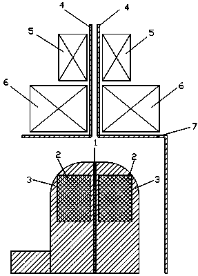
[0020] In order to solve the problems existing in the prior art that the realization of guided electron beam transmission is relatively difficult, the volume, weight and power consumption are high, the cost is expensive, and cannot meet the needs of technological development, such as figure 1 As shown, the present invention discloses a radial foil-free diode guided magnetic field system. The radial foil-free diode in the present invention includes a cathode support rod composed of a cylindrical conductor with a certain radius, and a circular conductor with a certain thickness The cathode emitter 1 is composed of an anode wall 7 composed of conductors (the first anode wall, the second anode wall, and the third anode wall) and a radial transmission line 4 composed of two mutually parallel conductors. The first anode wall and the second anode wall are located on both sides of the radial transmission line 4, respectively, and are connected to the corresponding conductors that const...


PUM


Abstract

The invention discloses a radial foil-free diode guiding magnetic field system which mainly solves the problems that in the prior art, the difficulty of implementation of electron beam transmission guiding is large, the size is large, the weight is heavy, the power consumption is high, the manufacturing cost is high, and the technological development requirements cannot be met. The radial foil-free diode guiding magnetic field system comprises a negative pole supporting rod (1), a transmission disc, a radial transmission wire (4), a first positive pole wall (2), a second positive pole wall (8) and a third positive pole wall (9), wherein the negative pole supporting rod (1) is formed by cylindrical conductors, the position below one side of the transmission disc is connected with the negative pole supporting rod (1), the transmission disc is formed by disc conductors, the radial transmission wire (4) is located right above the transmission disc, the first positive pole wall (2) and the second positive pole wall (8) are connected to the two sides of one end, which is closest to the transmission disc, of the radial transmission wire (4) respectively, the third positive pole wall (9) is located on the outer side of the transmission disc, and one end of the third positive pole wall (9) is connected with the other end, opposite to one end connected with the first positive pole wall (2) or the second positive pole wall (8), of the radial transmission wire (4). By means of the technical scheme, the radial foil-free diode guiding magnetic field system is easy to implement, achieves the aim of meeting the technological development requirements and has the high practical value and the high promotional value.

Description

technical field [0001] The invention relates to a guided magnetic field system, in particular to a radial non-foil diode guided magnetic field system in the combined focusing mode of a permanent magnet ring and a helical disk. Background technique [0002] In the development process of high-power microwave sources, high power, high frequency, high efficiency and miniaturization have become the development direction of most high-power microwave sources. Under the same beam current, the radial electron beam generated by using a foil-free diode with a larger emission cross-section has lower beam current density and space charge effect, which can reduce the intensity of the guiding magnetic field while obtaining higher beam conversion efficiency It is beneficial to achieve high efficiency and miniaturization of the system, and can avoid the problems of electron beam scattering and decrease of the transmission rate caused by the electron beam penetrating the anode net. [0003] ...

Claims


Application Information

Patent Timeline
Patent Type & Authority Applications(China)
IPC IPC(8): H01J23/087
Inventor 刘庆想李相强孔龙张健穹王邦继
Owner SOUTHWEST JIAOTONG UNIV
Why Eureka
Try Eureka