Fuel cell engine system

An engine system and fuel cell technology, applied in the direction of fuel cells, fuel cell additives, fuel cell parts, etc., can solve the problems of high energy consumption of cooling circulation pumps, large water delivery volume of cooling circulation pumps, etc., and achieve volume reduction and weight, reduce energy consumption, and simplify the system

Active Publication Date: 2013-12-25
SUNRISE POWER CO LTD
View PDF4 Cites 17 Cited by
  • Summary
  • Abstract
  • Description
  • Claims
  • Application Information

AI Technical Summary

Problems solved by technology

[0003] The fuel cell engine system in the prior art is equipped with an air cooler and a hydrogen preheater. The air cooler needs cooling circulating water to cool down, and the hydrogen preheater needs cooling circulating water to preheat. Since the amount of water required by the two is inconsistent, it is necessary to start from There are two branches in the cooling circulation pipeline, which respectively cool the air and preheat the hydrogen. The disadvantage is that the water delivery of the cooling circulation pump is large, and the energy consumption of the cooling circulation pump is large.

Method used


Image

  • Fuel cell engine system

Examples


Embodiment Construction

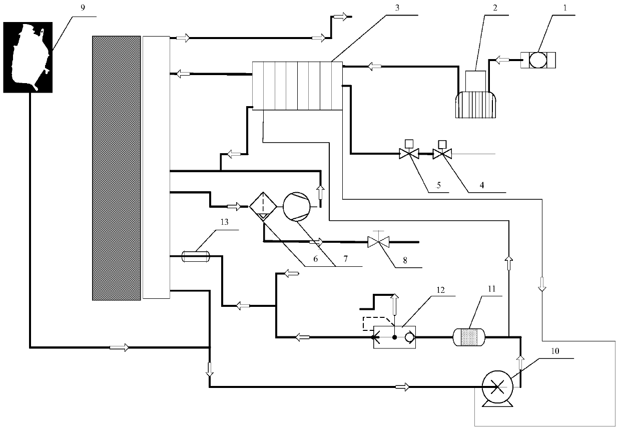
[0013] The present invention will be further described below in conjunction with drawings and embodiments.

[0014] Take the 50kW engine system as an example. The fuel cell engine system includes a fuel cell stack 14, a distribution assembly 15, a hydrogen supply unit, an air supply unit, a cooling unit and a heat exchanger 3, and the air supply unit includes a filter muffler 1 and an air compressor 2 connected by pipelines, The hydrogen supply unit includes a gas storage tank connected with a pipeline, a solenoid valve 4, a control valve 5, a water separator 6 and a hydrogen exhaust valve 8, and the cooling unit includes an expansion tank 9 connected with a pipeline, a cooling circulation pump 10, Filter 11, thermostat 12, and heating pipe 13. The air supply unit does not have a humidifier, and is replaced by a heat exchanger 3. The heat exchanger 3 is a three-stream heat exchanger, and the hot end of the heat exchanger 3 is an air fluid. The cold end of the heat exchanger 3...


PUM


Abstract

The invention discloses a fuel cell engine system, comprising a fuel cell stack, a distribution assembly, a hydrogen supply unit, an air supply unit, a cooling unit and a heat exchanger, wherein a humidifier of the air supply unit is omitted; the hydrogen supply unit comprises a hydrogen reflux part; the hot end of the heat exchanger is air fluid while the cold end of the heat exchanger is provided with two independent fluids, namely a hydrogen fluid and a cooling cycle fluid; the hot end inlet of the heat exchanger is connected with a vent of an air compressor while the hot end outlet is connected with an air inlet of the fuel cell stack; the two fluid inlets of the cold end of the heat exchange are respectively connected with a control valve outlet of a hydrogen storage tank outlet and a cooling cycle pump outlet; the two fluid outlets of the cold end of the heat exchanger are respectively connected with the fuel cell stack hydrogen inlet and cooling cycle pump inlet. The fuel cell engine system has the beneficial effects that the air cooler and the hydrogen preheater are combined, and hydrogen flux is used for replacing the air side humidifier, thus simplifying the system, reducing the size and weight of the parts, and reducing the system energy consumption.

Description

technical field [0001] The invention belongs to the field of fuel cells, in particular to a fuel cell engine system. Background technique [0002] In order to protect the environment and reduce air pollution in cities, devices powered by PEMFC (Proton Exchange Membrane Fuel Cell) have received more and more attention. When PEMFC is fueled by pure hydrogen, it can achieve true "zero" emissions. At present, PEMFC has certain applications in transportation, communication and other fields. [0003] The fuel cell engine system in the prior art is equipped with an air cooler and a hydrogen preheater. The air cooler needs cooling circulating water to cool down, and the hydrogen preheater needs cooling circulating water to preheat. Since the amount of water required by the two is inconsistent, it is necessary to start from There are two branches in the cooling circulation pipeline, which respectively cool the air and preheat the hydrogen. The disadvantage is that the water delivery...

Claims


Application Information

Patent Timeline
Patent Type & Authority Applications(China)
IPC IPC(8): H01M8/04H01M8/02H01M8/0297H01M8/04029H01M8/04791
CPCY02E60/50
Inventor 王仁芳侯中军戚朋江洪春胡景春沈鸿娟
Owner SUNRISE POWER CO LTD
Why Eureka
Try Eureka