Electronic components with reactive filters

A technology of electronic components and filters, which is applied in the direction of electronic switches, electrical components, output power conversion devices, etc., and can solve problems such as increased circuit loss

Active Publication Date: 2013-12-25
TRANSPHORM INC
View PDF9 Cites 58 Cited by
  • Summary
  • Abstract
  • Description
  • Claims
  • Application Information

AI Technical Summary

Problems solved by technology

Such filters require excessively large inductors and / or capacitors, resulting in a substantial increase in losses in the circuit
Furthermore, half-bridge inverters are limited to applications where the frequency of the signal transmitted to the electrical load 15 is much less than 1 kHz

Method used


Image

  • Electronic components with reactive filters
  • Electronic components with reactive filters
  • Electronic components with reactive filters

Examples


Embodiment Construction

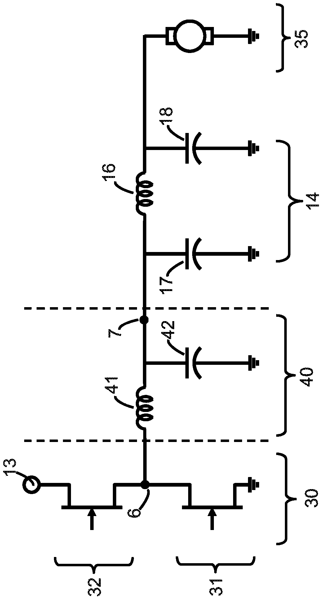
[0019] image 3 An inverter circuit is exemplified that is capable of outputting a sinusoidal AC waveform to an electrical load at a frequency greater than 1 kHz without substantially distorting or attenuating the waveform. The inverter circuit comprises a half bridge 30 connected to a filter 40 . As shown, the half bridge 30 includes two switches 31 and 32 connected. As shown, the low side terminal of switch 31 is grounded and the high side terminal of switch 32 is connected to high voltage power supply 13 . The filter 40 includes an inductance element 41 and a capacitance element 42 . The output 7 of the filter 40 is connected to an electrical load 35 by an electrical connector 14 such as a cable, at image 3 In , the electrical connector 14 is represented by a connected inductor 16 and capacitors 17 and 18 as shown.

[0020] Each of the switches 31 and 32 is capable of blocking a voltage at least equal to the voltage of the high-voltage power source 13 . That is, when ...


PUM


Abstract

An electronic component comprising a half bridge adapted for operation with an electrical load having an operating frequency is described. The half bridge comprises a first switch and a second switch each having a switching frequency, the first switch and the second switch each including a first terminal, a second terminal, and a control terminal, wherein the first terminal of the first switch and the second terminal of the second switch are both electrically connected to a node. The electronic component further includes a filter having a 3dB roll-off frequency, the 3dB roll-off frequency being less than the switching frequency of the switches but greater than the operating frequency of the electrical load. The first terminal of the filter is electrically coupled to the node, and the 3dB roll-off frequency of the filter is greater than 5 kHz.

Description

[0001] Cross References to Related Applications [0002] This application claims priority to US Provisional Application No. 61 / 447,519, filed February 28, 2011. The disclosure of this prior application is considered part of the present application and is hereby incorporated by reference in its entirety. technical field [0003] The invention relates to electronic components and modules for filtering voltage signals. Background technique [0004] Bridge circuits are commonly used to deliver AC voltage waveforms to electrical loads. figure 1 A general configuration of such a half-bridge inverter circuit is shown. The half-bridge 10 comprises two switches 11 and 12 each comprising a transistor 2 and 4 respectively, such as an IGBT or MOSFET, connected in anti-parallel to diodes 3 and 5 respectively, as shown. A pulse wave modulated (PWM) voltage source is used to control the gate voltage of each transistor of the switches 11 and 12 , resulting in a switching waveform at the ...

Claims


Application Information

Patent Timeline
Patent Type & Authority Applications(China)
IPC IPC(8): H02M1/12
CPCH03K17/687H02M1/126H02M7/5395H02P7/29H03K17/162H03K17/567H03K17/6871Y10T29/49105
Inventor 詹姆斯·霍尼亚吴毅锋
Owner TRANSPHORM INC
Why Eureka
Try Eureka