
Cutting and chamfering integrated turning tool and pipe cutting machine with one clamping and chamfering at the same time

A tube cutting machine and chamfering technology, which is applied in the attachment of tool holders, tools for lathes, clamping and other directions, can solve the problems affecting the next processing procedure and the improvement of processing accuracy, the roundness of the tube, and the cylindricity accuracy. Changes, large noise and pollution of the environment, etc., to avoid high equipment costs, reduce beating amplitude, and operate flexibly.

Inactive Publication Date: 2016-08-10
柳燕明
View PDF8 Cites 2 Cited by
  • Summary
  • Abstract
  • Description
  • Claims
  • Application Information

AI Technical Summary

Problems solved by technology

[0010] The noise pollutes the environment, the conical knife can only invert the inner corner of the end face of the pipe, and the outer corner cannot be inverted, and the chamfering of the file is labor-intensive, low in efficiency, and poor in quality.
[0011] The above four cutting and chamfering processing methods have one thing in common. In the mechanical clamping and fixing of the outer diameter of the thin-walled tube, not only the roundness and cylindricity accuracy of the round tube will be changed, but also the potential impact will be caused. The next process is based on the inner diameter of the material tube and the improvement of processing accuracy
[0012] The patent number is 201210264520.4, and the invention title is "differential pipe cutting machine for internal and external chamfering of both ends of the incision at the same time", which solves the problem of internal and external chamfering of both ends of the incision after the round tube is cut

Method used


Image

  • Cutting and chamfering integrated turning tool and pipe cutting machine with one clamping and chamfering at the same time
  • Cutting and chamfering integrated turning tool and pipe cutting machine with one clamping and chamfering at the same time
  • Cutting and chamfering integrated turning tool and pipe cutting machine with one clamping and chamfering at the same time

Examples


Embodiment 1

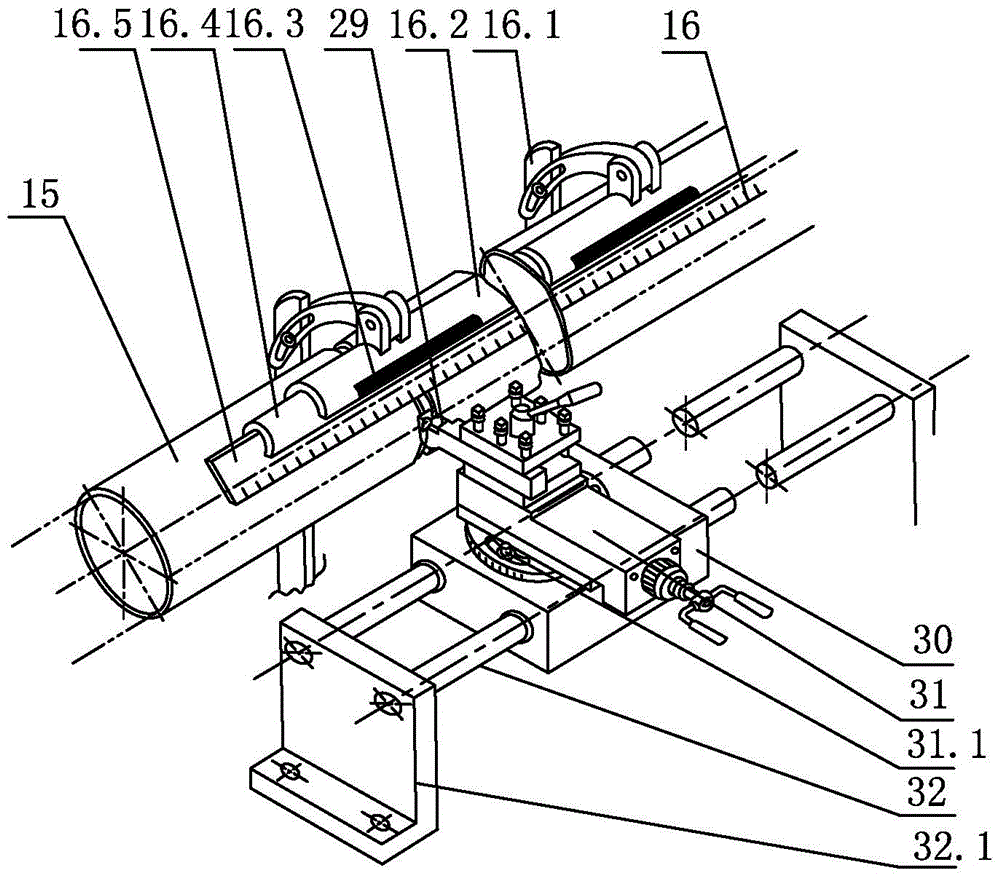
[0043] Such as Figure 4 As shown, a cutting and chamfering integrated turning tool includes a tool handle 29.8, a main cutting edge 29.4 is provided on the rake face 29.3, and two symmetrical edges are respectively provided on the intersecting edges of the rake face 29.3 and two symmetrical auxiliary flank faces 29.5. Minor cutting edge 29.1, two minor cutting edges 29.1 are respectively provided with two symmetrical V-shaped grooves 29.2, and the edge radian 29.7 of V-shaped groove 29.2 corresponds to the radian of the material tube 15 to be processed.

[0044] Operate the lathe tool holder so that the main cutting edge feeds radially towards the material tube. After cutting the material tube and retracting the tool slightly, move the cutting and chamfering integrated turning tool on the lathe tool holder axially left and right to use the V-shaped groove on the auxiliary cutting edge. Chamfering is performed on the inner and outer edges of the cross-section at both ends of t...

Embodiment 2

[0046] On the basis of Embodiment 1, the V-shaped groove 29.2 starts from the rake face 29.3 and is close to the main cutting edge 29.4, and the depth of the V-shaped groove 29.2 decreases gradually, and the width gradually decreases. The opening width of the V-shaped groove 29.2 is larger than the processed material. The wall thickness of the pipe 15 is 1-9mm away from the main cutting edge 29.4. In order to avoid the end face of the material pipe, the symmetrical secondary relief angle 29.6 below the secondary cutting edge is 1°-30°.

[0047] The size of the chamfer is determined by the opening width of the ground V-shaped groove, the size of the auxiliary relief angle, and the amount of left and right cutting.

Embodiment 3

[0049] On the basis of Embodiments 1 and 2, two symmetrical secondary cutting edges 29.1 formed by cutting off the rake face 29.3 of the chamfering integrated turning tool 29 and intersecting with two symmetrical secondary flank surfaces 29.5 are located near the front of the tool. , inclined downward, symmetrically provided with two gradually smaller V-shaped grooves 29.2, forming a side radian 29.7 of the V-shaped groove, corresponding to the radian of the cut material pipe 15.

[0050] The opening width of the V-shaped groove 29.2 starting from the rake face 29.3 is greater than the wall thickness of the cutting tube 15, the distance from the main cutting edge 29.4 is 1-9mm, and the symmetrical secondary relief angle 29.6 is 1°-30° .


PUM


Abstract

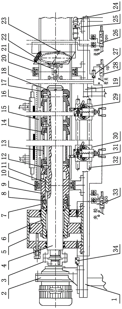
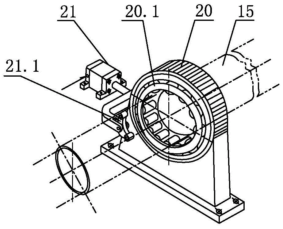
The invention relates to a cutting-off and chamfering integrated turning tool and a one-step clamping, cutting-off and chamfering pipe cutter and belongs to pipe machining equipment. A main cutting edge is arranged on a front tool surface of the front of a tool handle, and two V-shaped grooves are symmetrically arranged in two auxiliary cutting edges, so that both cutting-off and chamfering can be performed, the operation is flexible, and exchanging of different turning tools during chamfering are avoided. The cutting-off and chamfering integrated turning tool is used by the pipe cutter, a thrust bearing, a tapered wedge thrust pipe and a plurality of tapered wedge pipes which are mounted on a cylindrical shaft successively are connected together, and a rotary feed pipe is clamped firmly by outward expansion of C-shaped rings under thrust of a clamping air cylinder piston and tapered heads. By means of the cutting-off and chamfering integrated turning tool mounted on a sliding shaft lathe tool rest, within the range of clearance grooves of the tapered wedge pipes, during feed pipe cutting-off tool withdrawn, and on a device, during once clamp of the inner diameter of a thin-wall round pipe, a plurality of feed pipes can be cut off by setting the length, and chamfering is performed on inner and outer edges of two end faces of notches.

Description

technical field [0001] The invention relates to a cutting and chamfering integrated turning tool for cutting thin-walled round pipes and a pipe cutting machine for cutting and chamfering at the same time in one clamping. A turning tool for chamfering the inner and outer edges of both ends, and a pipe cutting machine using this turning tool. Background technique [0002] In industrial production, after the thin-walled round tube is cut, it is also required to chamfer the inner and outer edges of the two ends of the cut. At the same time, it is also required that the roundness accuracy of the material tube should not be damaged during the process of clamping the round tube. At present, the traditional tube cutting Processing mainly has the following four processing methods. [0003] 1. Lathe cutting and chamfering processing method: [0004] The outer diameter or inner diameter of the round pipe is clamped by the chuck of the lathe. When the pipe wall is about to be cut off,...

Claims


Application Information

Patent Timeline
Patent Type & Authority Patents(China)
IPC IPC(8): B23B27/00B23B5/08B23B25/00B23Q3/12
CPCB23B5/08B23B25/00B23B27/00B23Q3/12
Inventor 柳燕明马志远项业铭
Owner 柳燕明
Learn More