A method of heating cladding alloys on rails to solve poor branching

A technology for cladding alloys and bad shunting, applied in metal material coating process, coating, etc., can solve problems such as bad shunting, wear of alloy strips, waste of energy, etc., and achieve good shunting, concentrated heating, and utilization of thermal efficiency high effect

Active Publication Date: 2015-11-18
CHENGDU ZHONGGUI TECH CO LTD
View PDF3 Cites 0 Cited by
  • Summary
  • Abstract
  • Description
  • Claims
  • Application Information

AI Technical Summary

Problems solved by technology

[0008] Heating zone 1 and heating zone 2 constitute a three-dimensional structure. During specific heating, this structure makes the heating part of the rail only located on the outside of the rail tread and cannot move along the center of the rail tread and the inside of the rail tread, causing the alloy powder to only be clad On the outer side of the rail tread, with the long-term rolling of the wheels, the alloy strip after cladding will accelerate wear. When the relative height between the alloy strip and the rail tread is zero, if the alloy strip is only located on the outer side of the rail tread, it is possible that the wheel will contact Not reaching the alloy strip, resulting in poor shunting; in addition, the heating surface is two sides, the heating is more dispersed, and energy is wasted

Method used


Image

  • A method of heating cladding alloys on rails to solve poor branching
  • A method of heating cladding alloys on rails to solve poor branching

Examples


Embodiment 1

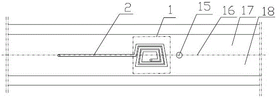
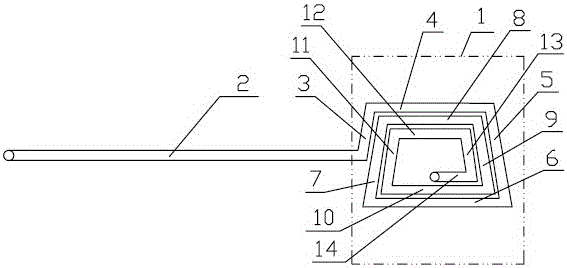
[0032]A method for heating cladding alloys on rails to solve poor shunting. The welding torch 15 is arranged above the rail tread to be clad, and the planar induction heater is arranged behind the welding torch 15. The planar induction heater is located at the same The first heating surface 1 and the second heating surface 2 are connected together on the horizontal plane. The first heating surface 1 is trapezoidal or square or circular, and the second heating surface 2 is in the shape of a "one". The horizontal position of the rail tread is adjustable. The welding torch 15 moves longitudinally along the rail tread to clad alloy powder on the rail tread to be clad to form an alloy strip. The planar induction heater also moves with the welding torch 15 and heats the rail tread. The moving speed of the planar induction heater Same as the moving speed of welding torch 15.

[0033] This embodiment is the most basic implementation. According to the wheel-rail contact theory, the whe...

Embodiment 2

[0035] A method for heating cladding alloys on rails to solve poor shunting. The welding torch 15 is arranged above the rail tread to be clad, and the planar induction heater is arranged behind the welding torch 15. The planar induction heater is located at the same The first heating surface 1 and the second heating surface 2 are connected together on the horizontal plane. The first heating surface 1 is trapezoidal or square or circular, and the second heating surface 2 is in the shape of a "one". The horizontal position of the rail tread is adjustable. The welding torch 15 moves longitudinally along the rail tread to clad alloy powder on the rail tread to be clad to form an alloy strip. The planar induction heater also moves with the welding torch 15 and heats the rail tread. The moving speed of the planar induction heater Same as the moving speed of welding torch 15. The rail tread to be clad refers to the center 16 of the rail tread or the inner side 17 of the rail tread or...

Embodiment 3

[0038] A method for heating cladding alloys on rails to solve poor shunting. The welding torch 15 is arranged above the rail tread to be clad, and the planar induction heater is arranged behind the welding torch 15. The planar induction heater is located at the same The first heating surface 1 and the second heating surface 2 are connected together on the horizontal plane. The first heating surface 1 is trapezoidal or square or circular, and the second heating surface 2 is in the shape of a "one". The horizontal position of the rail tread is adjustable. The welding torch 15 moves longitudinally along the rail tread to clad alloy powder on the rail tread to be clad to form an alloy strip. The planar induction heater also moves with the welding torch 15 and heats the rail tread. The moving speed of the planar induction heater Same as the moving speed of welding torch 15. The rail tread to be clad refers to the center 16 of the rail tread or the inner side 17 of the rail tread or...


PUM

PropertyMeasurementUnit
widthaaaaaaaaaa
heightaaaaaaaaaa
angleaaaaaaaaaa

Abstract

The invention discloses a method for preventing bad shunting through heating cladding alloy on a steel rail. A welding gun is arranged above the part to be clad of the steel rail tread; a planar inductive heater is arranged behind the welding gun and consists of a first heating surface and a second heating surface which are on the same horizontal plane and connected together; the first heating surface is trapezoidal, square or circular, and the second heating surface adopts a linear structure; the position of the planar inductive heater is adjustable in the transverse direction of the steel rail tread; the welding gun moves lengthways at the part to be clad of the steel rail tread along the steel rail tread to clad the alloy powder so as to form an alloy zone; the planar inductive heater moves together with the welding gun to heat the steel rail tread; the moving speed of the planar inductive heater is the same as that of the welding gun. The position of the planar inductive heater is adjustable in the transverse direction of the steel rail tread, and the alloy powder can be clad on the contact point of a wheel rail, so that the train wheels and the rail can be in contact conduction and favorable shunting of the track circuit is guaranteed.

Description

technical field [0001] The invention relates to the fields of metal material high-carbon steel surface cladding and railway track circuit signal control, in particular to a method for solving poor shunting by heating cladding alloys on rails. Background technique [0002] The track circuit is an electrical circuit composed of two rails of the railway line as conductors, and the signal power supply and receiving equipment are connected with lead wires. In sections where trains rarely pass through for a long time, such as shunting lines, cargo lines, special lines, and crossing lines, the rail surface is severely oxidized and rusted. Non-conductive, indicating that the track circuit has lost the function of checking the track section occupancy status. This phenomenon is called bad track circuit shunting, commonly known as "white light belt" or "undead". [0003] In the bad section of the railway track circuit, induction heating and plasma cladding are used to clad a layer of...

Claims


Application Information

Patent Timeline
Patent Type & Authority Patents(China)
IPC IPC(8): C23C24/10
Inventor 周厚全
Owner CHENGDU ZHONGGUI TECH CO LTD
Why Eureka
Try Eureka