Contra-rotating axial-flow fan with lateral external-type one-driving-two motor

An axial flow fan, external technology, applied in the direction of machines/engines, pump devices, mechanical equipment, etc., can solve the problems of difficult maintenance work, high manufacturing cost, low safety, etc.

Active Publication Date: 2014-01-01
PINGAN ELECTRICAL
View PDF6 Cites 10 Cited by
  • Summary
  • Abstract
  • Description
  • Claims
  • Application Information

AI Technical Summary

Problems solved by technology

[0012] The object of the present invention is to provide a side-to-side external motor one-to-two counter-rotating axial flow fan with more reliable work, longer service life, greatly reduced production cost, and more convenient inspection, maintenance and blade adjustment. Thoroughly solve the technical problems of the existing axial fans such as high manufacturing cost, low operation reliability, low safety, difficult maintenance and poor adaptability, and improve the working environment and stress condition of the motor

Method used


Image

  • Contra-rotating axial-flow fan with lateral external-type one-driving-two motor
  • Contra-rotating axial-flow fan with lateral external-type one-driving-two motor
  • Contra-rotating axial-flow fan with lateral external-type one-driving-two motor

Examples


Embodiment 1

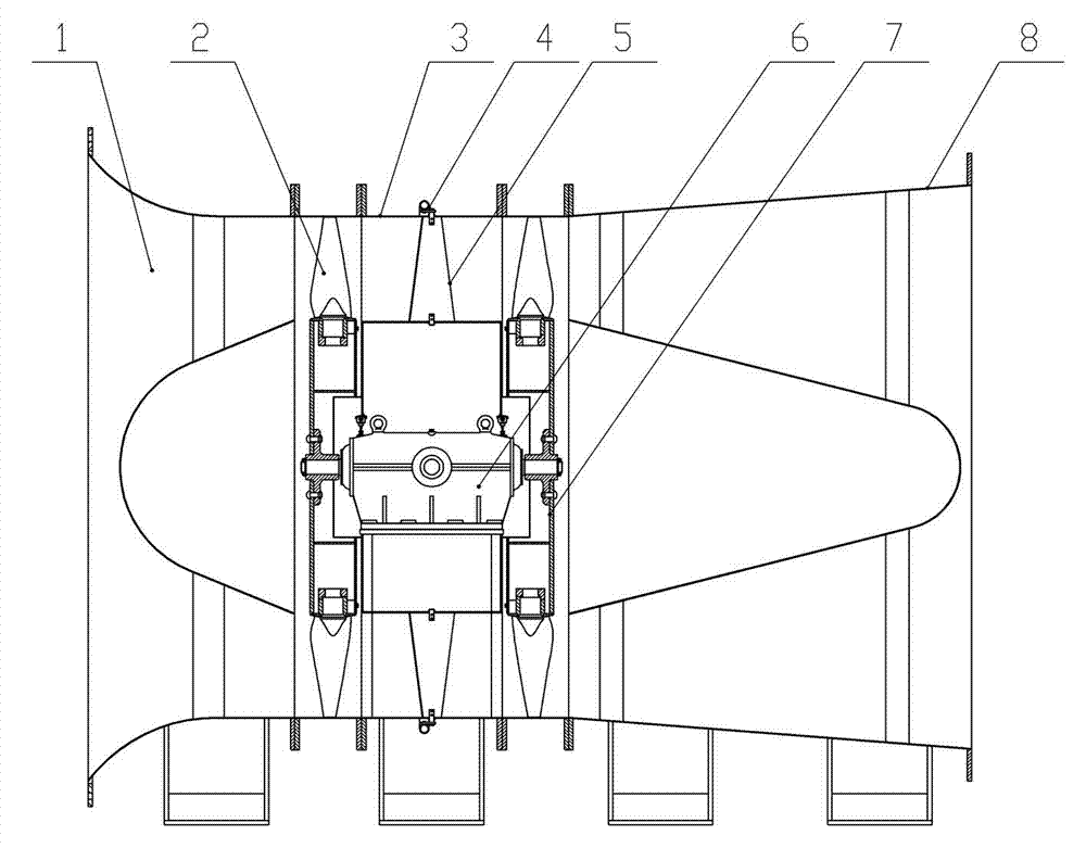
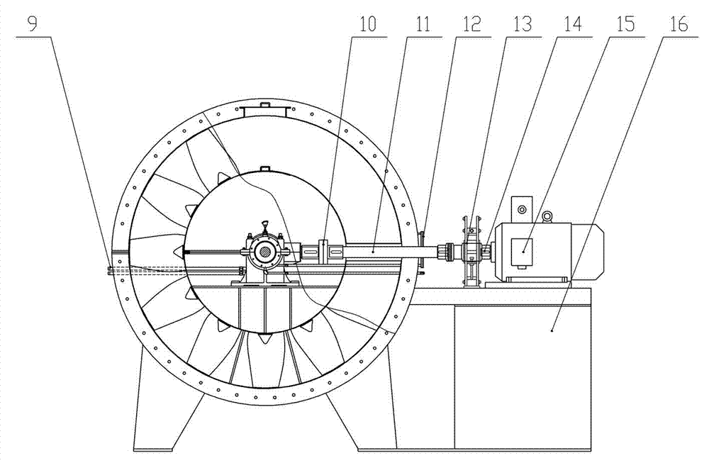
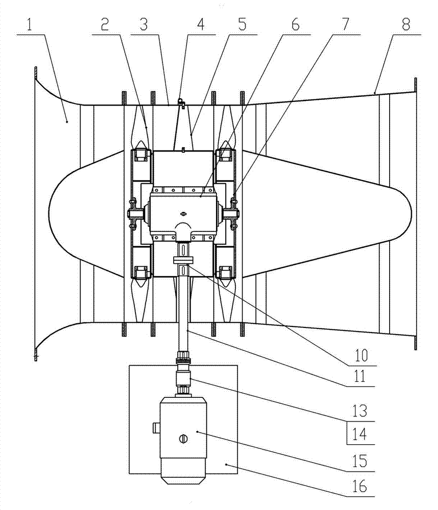
[0030] Embodiment 1, the present invention provides a motor lateral external one-to-two counter-rotating axial flow fan, which is characterized in that it includes a front impeller 2, a main engine cylinder 3, a guide vane adjustment mechanism 4, and a guide vane 5. Transmission box 6, rear impeller 7, internal coupling (10), transmission shaft 11, external coupling 14, motor 15 and motor support 16, main engine cylinder 3 includes outer cylinder and inner cylinder, inner and outer The annular space between the cylinders is the gas flow channel, and there are end plates at both ends of the inner cylinder to prevent or reduce harmful airflow entering the inner cylinder and affecting the transmission box. The transmission box 6 is installed on the machine base in the inner cylinder of the main engine cylinder body 3, the front impeller 2 and the rear impeller 7 are fixedly installed on the two output shafts of the transmission box 6, and guide vanes are arranged in the annular pa...

Embodiment 2

[0031] In Embodiment 2, a current collector 1 is arranged in front of the main engine cylinder body 3 to improve the efficiency of the fan, and a sound-absorbing diffuser cylinder 8 is arranged behind it to reduce the impact of noise. refer to Figure 1 to Figure 6 , all the other are with embodiment 1.

Embodiment 3

[0032]Embodiment 3, the transmission box 6 adopts a box-type structure, including an upper housing 601, a temperature sensor 602, a lower housing 603, a cooling water interface 604, a lubricating oil inlet and outlet interface 605, an output shaft 606, a gland 607, and an oil seal 608 , bearing 609, driven bevel gear 610, lock nut 611, driving bevel gear 612 and input shaft 613, an oil storage cavity, a cooling water interface 604 and a lubricating oil inlet and outlet interface 605 are arranged in the transmission box 6, and the oil storage cavity It does not communicate with the cooling water channel. The transmission box housing is composed of an upper housing 601 and a lower housing 603. The lower housing 603 acts as a support and oil storage. There are two output shafts 606 in the middle of the housing. The output shaft 606 and the bearing 609, the outer side of the bearing 609 is equipped with an oil seal 608 and a gland 607, the output shaft 606 and the input shaft 613 a...


PUM


Abstract

The invention relates to a contra-rotating axial-flow fan with a lateral external-type one-driving-two motor. The contra-rotating axial-flow fan with the lateral external-type one-driving-two motor mainly solves the technical problems that the manufacturing cost of the existing axial-flow fan is high, the operation reliability and safety are lower, the working difficulty in maintenance is great and the like, and improves the operating environment and the stress situation of the motor are improved. The technical scheme is that a front impeller (2) and a rear impeller (7) are fixedly and respectively installed on two output shafts of a transmission case (6) on a base in an inner cylinder of a main machine cylinder (3), flow guide blades (5) and a flow guide blade adjusting mechanism (4) are arranged in an annular passage between the two impellers, a motor support (16) is arranged outside the lateral direction of the main machine cylinder (3) and a motor (15) which is installed on the motor support (16) is connected with the transmission case (6). The contra-rotating axial-flow fan with the lateral external-type one-driving-two motor is a ventilation device which can be widely used in industries such as mining, metallurgy, chemical industry and power plants and can be especially used for working places of explosion, high temperature, corrosion and the like.

Description

technical field [0001] The invention relates to a ventilator, in particular to an axial flow ventilator. Background technique [0002] At present, the ventilator is a general-purpose machine widely used in various industries of the national economy. There are two types of centrifugal fans and axial fans. The so-called axial flow fan refers to the fan in which the airflow flows along the axial direction in the flow channel of the rotating blade on the axial section. The circumferential direction is evenly arranged on the hub, and the hub is fixedly installed on the motor shaft extension arranged along the axial direction, and the motor is arranged axially along the cylinder. Due to the characteristics of large flow, small volume and low pressure head, this fan is mainly used in various ventilation systems that require large flow. In order to increase the pressure, it is often used in the form of multi-stage combination when it is applied to the ventilation system with long...

Claims


Application Information

Patent Timeline
Patent Type & Authority Applications(China)
IPC IPC(8): F04D25/08F04D25/16
Inventor 谢星明陈重新肖务里王海桥
Owner PINGAN ELECTRICAL
Why Eureka
Try Eureka