
Automatic safe control device of industrial waste heat recovery system

A safety control and recovery system technology, applied in heat exchange equipment, lighting and heating equipment, etc., can solve the problems of heat pipe heat exchanger such as large thermal stress, burst, heat transfer adjustment, etc., and achieve the effect of overcoming dew point corrosion problems

Active Publication Date: 2014-01-01
INST OF ENGINEERING THERMOPHYSICS - CHINESE ACAD OF SCI
View PDF5 Cites 5 Cited by
  • Summary
  • Abstract
  • Description
  • Claims
  • Application Information

AI Technical Summary

Problems solved by technology

[0004] However, in the existing industrial waste heat recovery systems using heat pipe heat exchangers, after the structure of the heat pipe heat exchanger is determined, its heat transfer capacity is difficult to adjust according to the heat transfer demand of the system. The inside of the heat pipe heat exchanger will generate a lot of thermal stress and even burst

Method used


Image

  • Automatic safe control device of industrial waste heat recovery system

Examples


Embodiment Construction

[0022] In order to make the object, technical solution and advantages of the present invention clearer, the present invention will be described in further detail below in conjunction with specific embodiments and with reference to the accompanying drawings. It should be noted that, in the drawings or descriptions of the specification, similar or identical parts all use the same figure numbers. Implementations not shown or described in the accompanying drawings are forms known to those of ordinary skill in the art. Additionally, while illustrations of parameters including particular values ​​may be provided herein, it should be understood that the parameters need not be exactly equal to the corresponding values, but rather may approximate the corresponding values ​​within acceptable error margins or design constraints. The directional terms mentioned in the embodiments, such as "upper", "lower", "front", "rear", "left", "right", etc., are only referring to the directions of the...


PUM


Abstract

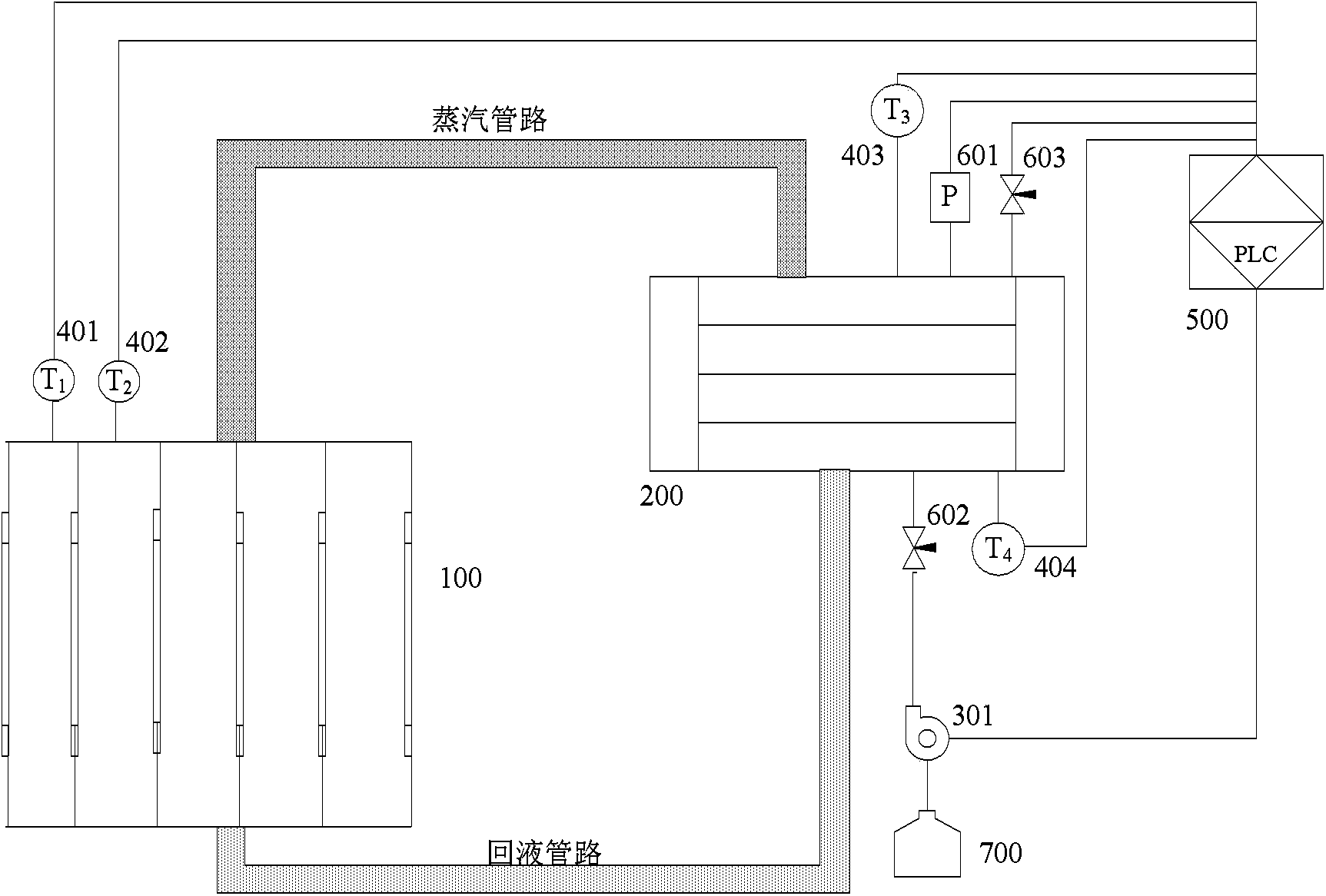
The invention provides an automatic safe control device of an industrial waste heat recovery system. The automatic safe control device is based on the industrial waste heat recovery system. Temperature sensors are mounted on a heat-pipe-type cooler and are used for measuring the temperature; the port of a condenser is provided with a temperature sensor for measuring the cooling amount of the entire system, and a pressure sensor is mounted on the condenser for measuring the pressure of working fluid inside the system; signals of the sensors are inputted into the control system, and safe and effective utilization of industrial waste can be realized by controlling the number of the working fluid inside the system.

Description

technical field [0001] The invention relates to the field of automatic control, in particular to an automatic safety control device for an industrial waste heat recovery system. Background technique [0002] Industrial waste heat generally exists in electric power, metallurgy, chemical industry and other industries, and the flue gas at the tail of the boiler contains huge heat, so how to take out the heat in the flue gas and make full use of the above energy is one of the main research contents of energy saving and emission reduction. At present, the high-efficiency heat exchange methods in the utilization of industrial waste heat mainly include the following two types: direct heat exchange by heat exchangers and heat pipe heat exchangers. For the direct heat exchange method of the heat exchanger, since the heated substance directly exchanges heat with the flue gas, the temperature difference is large, which easily leads to corrosion on the surface of the heat exchanger and ...

Claims


Application Information

Patent Timeline
Patent Type & Authority Applications(China)
IPC IPC(8): F28F27/00
Inventor 王涛胡学功郭朝红于东郭聪唐大伟
Owner INST OF ENGINEERING THERMOPHYSICS - CHINESE ACAD OF SCI
Learn More