
Reactive compensation device and method for partially regulating voltages and capacitance of three-phase four-wire power grid

A three-phase four-wire system, compensation device technology, applied in reactive power compensation, reactive power adjustment/elimination/compensation and other directions, can solve the problems of low load power factor, frequent load changes, large capacity of autotransformers, etc. The service life is consistent, the compensation accuracy is improved, and the effect of eliminating the inrush current

Active Publication Date: 2015-07-22
GUILIN UNIV OF ELECTRONIC TECH
View PDF5 Cites 0 Cited by
  • Summary
  • Abstract
  • Description
  • Claims
  • Application Information

AI Technical Summary

Problems solved by technology

[0002] The three-phase four-wire power grid has the disadvantages of serious three-phase load imbalance, frequent load changes, and low load power factor, which is not conducive to the safe and efficient operation of the power grid.
This reactive power compensation technology generally uses an autotransformer as a voltage regulating device, but the autotransformer itself is a device that consumes energy and generates reactive power. The large capacity of the autotransformer is extremely unfavorable to economic operation.

Method used


Image

  • Reactive compensation device and method for partially regulating voltages and capacitance of three-phase four-wire power grid
  • Reactive compensation device and method for partially regulating voltages and capacitance of three-phase four-wire power grid

Examples


Embodiment Construction

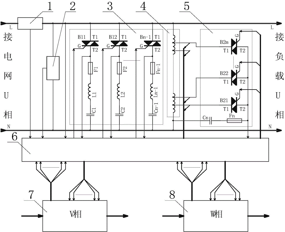
[0026] A reactive power compensation device for partial voltage regulation and capacity regulation of a three-phase four-wire power grid, such as figure 1 As shown, it includes U-phase, V-phase and W-phase voltage regulation and capacity regulation reactive power compensation units and a control unit 6 . The reactive power compensation unit for each phase voltage regulation and capacity regulation is mainly composed of a current detection element 1, a voltage detection element 2, a full voltage compensation capacitor group 3, an auto-transformer 4 and a voltage regulation capacitor group 5.

[0027] The following takes the U-phase voltage regulation and capacity regulation reactive power compensation unit as an example to describe each phase voltage regulation and capacity regulation reactive power compensation unit in detail:

[0028] The U-phase current detection element 1 is connected in series with the live line of the U-phase of the power grid, the U-phase voltage detecti...


PUM


Abstract

The invention discloses a reactive compensation device and method for partially regulating voltages and capacitance of a three-phase four-wire power grid. The reactive compensation device comprises a U-phase voltage and capacitance regulating reactive compensation unit, a V-phase voltage and capacitance regulating reactive compensation unit, a W-phase voltage and capacitance regulating reactive compensation unit and a control unit. Each phase of voltage and capacitance regulating reactive compensation unit is mainly composed of a current detection element, a voltage detection element, a full-voltage compensation capacitor bank, an auto-transformer and a voltage-regulating capacitor bank. The control mode of independent reactive compensation in each phase is used in the three-phase four-wire power grid, total capacitance in each phase is uniform, the capacitance in each phase is evenly divided into n sets, wherein one set of the capacitance is subjected to voltage and capacitance regulation through the auto-transformer which totally has m levels of output voltages, each phase has n*m grades of compensation, and multi-level fine compensation for the power grid is achieved.

Description

technical field [0001] The invention relates to reactive power compensation of a three-phase four-wire power grid, and belongs to the technical field of automatic reactive power compensation of parallel capacitors controlled by thyristors, in particular to a reactive power compensation device and method for partial voltage regulation and capacity adjustment of a three-phase four-wire power grid. Background technique [0002] The three-phase four-wire power grid has the disadvantages of serious three-phase load imbalance, frequent load changes, and low load power factor, which is not conducive to the safe and efficient operation of the power grid. Reactive power compensation is an important means to maintain grid voltage stability and maintain the safe operation of the power system, and shunt capacitors are an important means of reactive power compensation for the grid. The conventional capacitor compensation device adopts the simultaneous switching mode of three equal capaci...

Claims


Application Information

Patent Timeline
Patent Type & Authority Patents(China)
IPC IPC(8): H02J3/18
CPCY02E40/30
Inventor 韦寿祺刘志杰苏振源陈叙黎明李雪娇崔九喜
Owner GUILIN UNIV OF ELECTRONIC TECH
Learn More