
Laser-mig Composite Heat Source Welding Method for Thick Aluminum Alloy

A composite heat source and welding method technology, which is applied in laser welding equipment, welding equipment, metal processing, etc., can solve the problems of poor penetration ability and many pores, and achieve strong penetration ability, stable welding process, and stable laser welding process Effect

Active Publication Date: 2016-03-23
恒普(宁波)激光科技有限公司
View PDF5 Cites 0 Cited by
  • Summary
  • Abstract
  • Description
  • Claims
  • Application Information

AI Technical Summary

Problems solved by technology

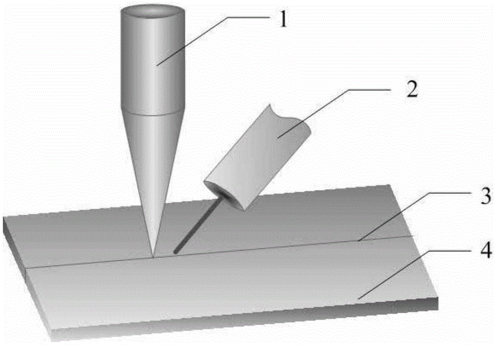
[0004] The purpose of the present invention is to provide a laser-MIG composite heat source welding method for thick plate aluminum alloys in order to solve the technical problems of poor penetration ability and more air holes in the existing welding method for aluminum alloy materials

Method used


Image

  • Laser-mig Composite Heat Source Welding Method for Thick Aluminum Alloy
  • Laser-mig Composite Heat Source Welding Method for Thick Aluminum Alloy
  • Laser-mig Composite Heat Source Welding Method for Thick Aluminum Alloy

Examples


specific Embodiment approach 1

[0019] Specific implementation mode 1: In this implementation mode, the laser-MIG composite heat source welding method for thick plate aluminum alloy is as follows:

[0020] 1. Soak the thick plate aluminum alloy workpiece to be welded in acetone for 5-8 minutes, then put it in an aqueous solution of sodium hydroxide with a mass concentration of 5-8% at 40-50°C for 4-10 minutes, and clean it with water. Rinse, then soak in nitric acid with a mass concentration of 20-30% for 2-4 minutes, rinse with water, and dry at 80°C for 30 minutes;

[0021] 2. Fix the thick-plate aluminum alloy workpiece to be welded on the workbench after step 1, and the welding assembly gap of the thick-plate aluminum alloy workpiece to be welded is less than 15% of the thickness of the thick-plate aluminum alloy workpiece to be welded;

[0022] 3. The laser generator is used to emit the laser beam, and the gas-shielded welding power source is used to generate an arc at the same time, and the laser-MIG c...

specific Embodiment approach 2

[0026] Specific embodiment 2: The difference between this embodiment and specific embodiment 1 is that the laser beam described in step 3 is CO 2 Gas laser beam, Nd:YAG solid-state laser beam, semiconductor laser beam or fiber laser beam. Others are the same as in the first embodiment.

specific Embodiment approach 3

[0027] Embodiment 3: This embodiment differs from Embodiment 1 or Embodiment 2 in that in step 1, it is placed in nitric acid with a mass concentration of 25%, soaked for 3 minutes, and then rinsed with water. Others are the same as those in the first or second embodiment.


PUM

PropertyMeasurementUnit
diameteraaaaaaaaaa

Abstract

The invention relates to a welding method, in particular to a laser-MIG composite heat source welding method for a thick plate aluminum alloy, and aims to solve the technical problems that according to an existing welding method for aluminum alloy material, penetration capacity is poor, and many pores are formed. The laser-MIG composite heat source welding method includes the steps that (1), a thick plate aluminum alloy workpiece to be welded is subjected to chemical cleaning; (2), the thick plate aluminum alloy workpiece to be welded is fixed on a working table after undergoing the treatment in the step (1), and the weld assembling clearance of the thick plate aluminum alloy workpiece to be welded is smaller than 15% of the thickness of the thick plate aluminum alloy workpiece to be welded; (3), a laser generating device is adopted for emitting laser beams, a consumable electrode metal-inert gas welding (MIG) power source is simultaneously adopted for generating electric arcs, and then laser-MIG composite heat source welding is carried out. According to the laser-MIG composite heat source welding method, the penetration capacity is high, the welding process is stable, and weld pores are few. The invention belongs to the field of welding.

Description

technical field [0001] The invention relates to a welding method. Background technique [0002] Aluminum alloy is widely used in many important fields of national defense and economic construction because of its good physical, chemical and mechanical properties. As an important light metal structural material, in addition to the aerospace industry, high-strength aluminum alloys are also increasingly used in high-speed trains, light vehicles, etc., to meet the ever-increasing structural lightweight requirements of transportation vehicles. In recent years, with the rise of energy saving and emission reduction, automobile lightweight has received more and more attention. The use of aluminum alloy instead of steel plate material for welding can greatly reduce the structural weight, making aluminum and aluminum alloy a very competitive energy-saving and emission-reducing material. [0003] Although the application potential of aluminum alloy in the automobile industry and other...

Claims


Application Information

Patent Timeline
Patent Type & Authority Patents(China)
IPC IPC(8): B23K26/348B23K103/10
CPCB23K26/348B23K26/60B23K2101/185B23K2103/10
Inventor 不公告发明人
Owner 恒普(宁波)激光科技有限公司
Learn More