Manufacturing method of composite material laminated plate with holes

A composite material layer and manufacturing method technology, applied in the field of composite materials, can solve the problems of reducing strength, fiber breakage, reducing the strength of composite material laminates, etc.

Inactive Publication Date: 2014-01-08
CHONGQING UNIV
View PDF6 Cites 20 Cited by
  • Summary
  • Abstract
  • Description
  • Claims
  • Application Information

AI Technical Summary

Problems solved by technology

Chinese Patent No. 201010132202.5 discloses a "laser precision hole-making method and device for fiber composite aircraft siding". The laser non-contact hole-making method overcomes the problems of wire drawing and separation caused by drilling force when drilling with a drill bit. layer, fiber breakage, cutting residual stress and deformation, etc.
[0004] The problem with existing hole-making methods for composite laminates is that the fibers at the holes in the composite are cut, reducing the strength of the composite laminate and the assembled composite structure
Existing methods for making holes in composite laminates also cause damage such as wire drawing and delamination at the edge of the hole, and also reduce the strength of the composite laminate and the assembled composite structure, making the hole and the vicinity of the hole in the composite laminate a whole The most dangerous place for fracture damage of composite laminates and composite structures

Method used


Image

  • Manufacturing method of composite material laminated plate with holes
  • Manufacturing method of composite material laminated plate with holes

Examples


Embodiment Construction

[0022] Below in conjunction with accompanying drawing and embodiment the present invention will be further described:

[0023] The invention includes

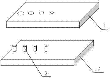
[0024] Step 1. Mold preparation

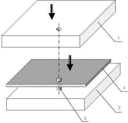
[0025] Such as figure 1 As shown, a row of through holes are set on the upper mold plate 1 and the lower mold plate 2, and pins 3 of corresponding sizes are made corresponding to the through holes of the mold plate. One end of the pin 3 is flat, and the other end is chamfered. Make the fiber easily bypass the cylindrical pin, and insert the flat end of the pin into the lower mold plate 2; the size, shape and position of the pin 3 determine the size, shape and position of the hole in the composite material laminate, and the hole in the composite material laminate is based on the actual Depends on usage;

[0026] Step 2. Fabrication and dipping of fiber cloth

[0027] Cut the fiber cloth to a suitable size according to the size of the mold, then fully soak the fiber cloth with resin, and dry ...


PUM


Abstract

The invention discloses a manufacturing method of a composite material laminated plate with holes. The manufacturing method comprises the following steps: a step I of forming through holes in upper and lower mould boards, manufacturing pins with corresponding dimensions corresponding to the through holes of the mould boards, wherein one end of each of the pins is a flat end, and the other end of each of the pins is machined with chamfer, and the flat end of each of the pins is inserted into the lower mould board; a step II of manufacturing and gum dipping of fiber cloths; a step III of coating a de-molding agent on the upper and lower mould boards and the pins, laminating the fiber cloths under a semi-dried state according to a preset fiber direction of the composite material laminated plate, and enabling fibers in each layer of the filter cloths to bypass pins in the lower mould board during laminating; a step IV of compounding the mould boards to carry hot-pressing and curing; and a step V of opening a mould. The manufacturing method disclosed by the invention has the advantage that fibers at holes of the composite material laminated plate are retained and reasonably distributed near the holes of the composite material laminated plate, so that strength of the composite material laminated plate with holes is far greater than that of a composite material laminated plate with holes obtained by an existing hole-making method.

Description

technical field [0001] The invention relates to composite materials, in particular to a method for manufacturing a composite material laminate with holes. Background technique [0002] Composite laminates (or shells) are in many cases impossible to achieve the required size and shape due to process limitations. Therefore, it is often necessary to connect them to each other. The main method of joining composite laminates is through screws or pins, and to install these screws or pins, there must be holes in the composite laminate to fit the screws or pins. [0003] At present, the common preparation method of composite laminates with holes is to adopt mechanical processing methods: firstly prepare composite laminates by molding method, and then perform mechanical processing such as drilling or punching on the obtained composite laminates to obtain the required holes. The Chinese patent application number is 201210399254.6, titled "Drilling Force Control Based Non-Layer Dril...

Claims


Application Information

Patent Timeline
Patent Type & Authority Applications(China)
IPC IPC(8): B29C70/34B29C70/54
CPCB29C70/345B29C70/54
Inventor 陈斌
Owner CHONGQING UNIV
Why Eureka
Try Eureka