

High-temperature alloy rib structure laser solid forming method
A technology of high-temperature alloys and ribs, which is applied in the coating process and coating of metal materials, can solve the problems of increased cost, high cost, and long cycle, and achieve the effect of improving the overall strength and rigidity
- Summary
- Abstract
- Description
- Claims
- Application Information
AI Technical Summary
Problems solved by technology
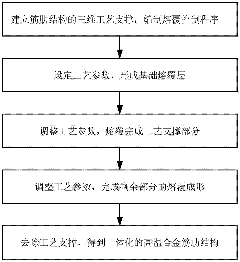
Method used
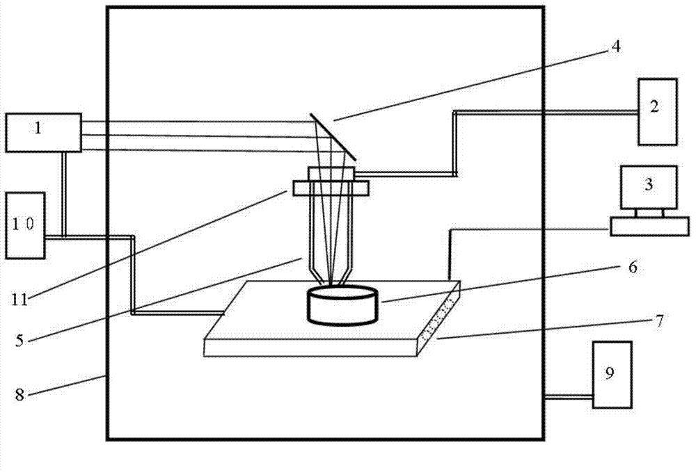
Image

Examples
Embodiment 1
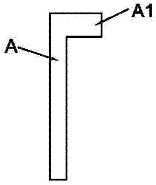
[0041] This embodiment manufactures a titanium alloy process sample A with a width of 60mm, a height of 100mm, a thickness of 10mm, and a 15mm boss on the top, such as Figure 3a As shown, A1 in the figure is the boss. The specific manufacturing steps are as follows:
[0042] 1. Select a TC4 titanium alloy plate with a thickness of about 60mm×10mm×10mm as the substrate, simulate the semi-finished parts, and fix them on the machine tool with fixtures;
[0043] 2. Turn on the laser, set the laser power parameter to 700W, high-purity CO 2 , high-purity He, high-purity N 2 The pressure is adjusted to about 0.5MPa, and the cooling water flow is about 20L / min;
[0044] 3. Put the titanium alloy powder into the powder feeder;
[0045] 4. Use UG software to establish a three-dimensional model of titanium alloy process sample 1 and process support 1B. The shape of process support A2 is as follows Figure 3b As shown, the slope α is 10°, and the 3D model is subdivided using the sub...
Embodiment 2
[0051] This embodiment manufactures the titanium alloy cabin section test piece B with ring rib structure, Figure 4a is the longitudinal sectional view of the side wall of the cabin with ring ribs, where B1 is the position of the ring ribs. Its specific manufacturing steps are as follows:
[0052] 1. Fix the semi-finished titanium alloy cabin section on the machine tool with fixtures;
[0053] 2. Turn on the laser, set the laser power parameter to 1000W, high-purity CO 2 , high-purity He, high-purity N 2 The pressure is adjusted to about 0.5MPa, and the cooling water flow is about 20L / min;
[0054] 3. Put the titanium alloy powder into the powder feeder;
[0055] 4. Use UG software to establish a three-dimensional model of the technical support of the ring reinforcement, and merge it with the titanium alloy cabin model. The shape of the technical support B2 is as follows Figure 4b As shown, the slope α is 15°. The 3D model is subdivided using the subdivision software th...
PUM
| Property | Measurement | Unit |
|---|---|---|
| particle size | aaaaa | aaaaa |
| particle size | aaaaa | aaaaa |
Abstract
Description
Claims
Application Information