Small-sized mixed-flow pump turbine for low water head pumped storage power station

A pumped-storage power station and pump-turbine technology, applied in the field of hydraulic machinery, can solve the problems of reduced unit efficiency, difficulty in guaranteeing dimensional accuracy, and high construction cost, and achieve high energy recovery efficiency, small flow channel resistance loss, and small amount of civil engineering. Effect

Inactive Publication Date: 2014-01-08
HOHAI UNIV +1
View PDF6 Cites 22 Cited by
  • Summary
  • Abstract
  • Description
  • Claims
  • Application Information

AI Technical Summary

Problems solved by technology

[0003] Chinese patent application 200810010743.1 discloses a "pump turbine", which provides a micro-pump turbine with simple structure, low cost, small flow rate, and small volume. The runner needs to be replaced when the working conditions are interchanged, which brings great restrictions to continuous production and operation; second, the manufacturing process of the airfoil blade is extremely complicated, and the dimensional accuracy is difficult to guarantee, which directly affects the operating ef...

Method used


Image

  • Small-sized mixed-flow pump turbine for low water head pumped storage power station
  • Small-sized mixed-flow pump turbine for low water head pumped storage power station
  • Small-sized mixed-flow pump turbine for low water head pumped storage power station

Examples


Embodiment Construction

[0018] The specific implementation manners of the present invention will be further described in detail below in conjunction with the drawings and examples.

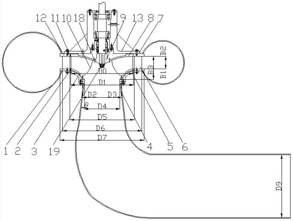
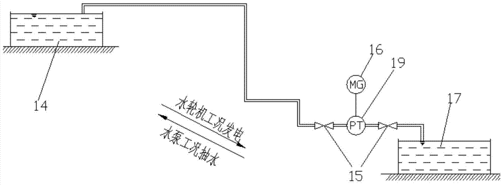
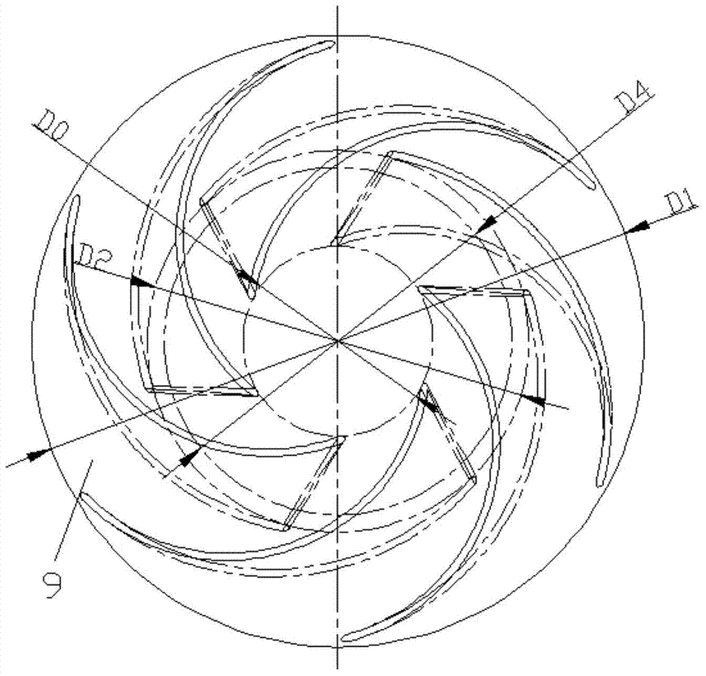
[0019] combine figure 1 , image 3 , Figure 7 , a small Francis pump-turbine used in a low-head pumped storage power station proposed by the present invention, which includes a volute (1), a draft pipe (4), a runner chamber (5), guide vanes (6), an upper Cover (7), runner (9), seat ring (12) and bearing end cover (13), in which: volute (1), guide vane (6), runner (9) and draft tube (4) in sequence connection, the runner (9) includes the runner blade (2), the lower ring (3), the upper crown (8) and the drain cone (19), the upper cover (7) is set on the runner (9), and the bearing end The cover (13) is arranged on the upper cover (7), the wrapping angle of the runner blade (2) is 105°~124°, the water inlet side (11) and the water outlet side (10) of the runner blade (2) The angle between the runner blades (2) is 54°~...


PUM

PropertyMeasurementUnit
Angleaaaaaaaaaa
Wrap angleaaaaaaaaaa

Abstract

The invention relates to a small-sized mixed-flow pump turbine for a low water head pumped storage power station. The small-sized mixed-flow pump turbine for the low water head pumped storage power station is characterized in that the wrap angle of runner blades is 105-124 degrees, the included angle between the water inlet edge of each runner blade and the water outlet edge of the runner blade is 54-86 degrees, each runner blade is a three-dimensional distorted curved face, the thicknesses are equal in the perpendicular spine direction, the profile of each runner blade is crescent, the ratio value of the thickness of each runner blade to the height B1, existing under the working conditions of the turbine, of an inlet of each runner blade is 0.06-0.11, the height B1, existing under the working conditions of the turbine, of an inlet of each runner blade is equal to the height B2 of each guide vane, a wing of each guide vane is of a symmetrical whale shape, the upper canopy of each guide vane is provided with three pressure-relief vents which are evenly distributed, the axial section of a volute is round, a draft tube is of an elbow shape, and the axial section of the horizontal and straight section of the draft tube is round. By the adoption of the small-sized mixed-flow pump turbine for the low water head pumped storage power station, the water pump pumping working condition and the turbine electricity generation working condition which are opposite in directions of water flow pumped for two times, and the water turbine can efficiently operate under the two operation working conditions.

Description

technical field [0001] The invention belongs to the technical field of hydraulic machinery, in particular to a small mixed-flow pump-turbine used in a low-head pumped storage power station. Background technique [0002] With the rapid expansion and development of the power system, the functions of pumped storage power plants in the power system, such as peak regulation, frequency regulation, phase regulation and emergency backup, are becoming more and more significant. The pumped storage unit is the main unit of the pumped storage power station. The current pumped storage unit is mainly a reversible pump-turbine that can operate in both directions, and it has the functions of both a water turbine and a water pump. At present, there have been relatively in-depth researches on medium-high head and large-capacity pump turbines at home and abroad, and many experiences in design, optimization, and operation have been accumulated, and good results have been achieved. At the same ...

Claims


Application Information

Patent Timeline
IPC IPC(8): F03B3/12
CPCY02E10/223Y02E10/20
Inventor 郑源毛秀丽屈波
Owner HOHAI UNIV
Why Eureka
Try Eureka