Electric hand rubbing bionic device

A two-handed, electric technology, applied in electromechanical devices, transmission devices, electric components, etc., can solve the problems of high cost, high cost, complex structure, etc., and achieve the effects of high work reliability, widespread use, and simple structure

Active Publication Date: 2016-08-17
SUZHOU UNIV
View PDF7 Cites 0 Cited by
  • Summary
  • Abstract
  • Description
  • Claims
  • Application Information

AI Technical Summary

Problems solved by technology

This not only makes the whole device extremely large and complex, but also extremely expensive
For example, the kneading massager disclosed in Chinese patent document CN 102940566 A is not only extremely complicated in structure, but also fails to give the trajectory of bionic motion; another example is the numerically controlled rubbing type grinding machine disclosed in Chinese patent document CN 103252709 A, which uses three servo The motor, as well as the extremely complex mechanical transmission system, is bulky and expensive
From a kinematic point of view, no substantial hands-rubbing bionic device has yet been retrieved

Method used


Image

  • Electric hand rubbing bionic device
  • Electric hand rubbing bionic device
  • Electric hand rubbing bionic device

Examples


Embodiment 1

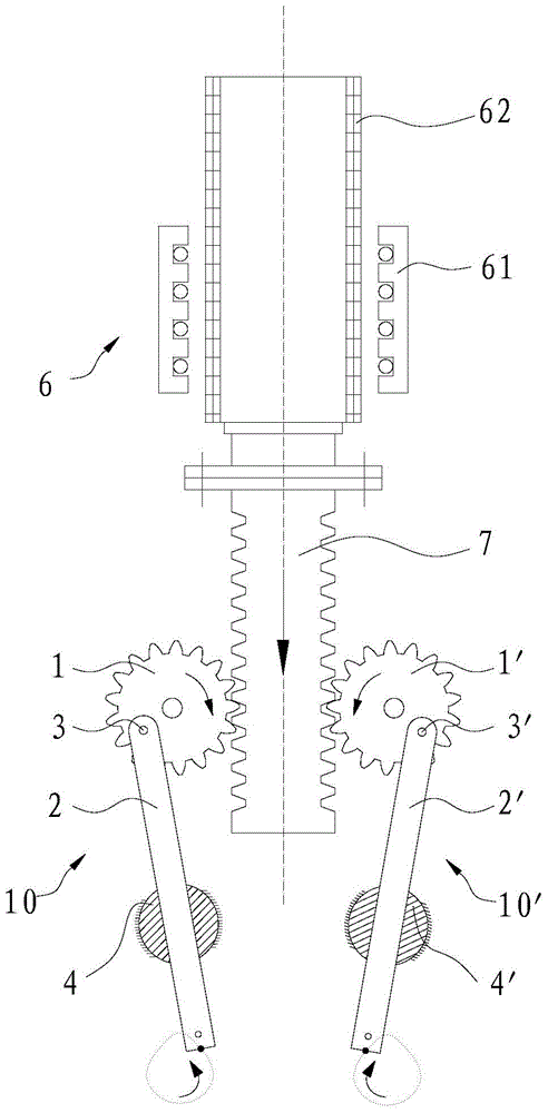
[0023] see picture 1 An electric hands rubbing bionic device shown, including a frame (not shown in the figure), two sets of rubbing components arranged on the frame 10 、 10’ , set on the frame for driving the kneading components 10 、 10’ working linear motor 6 and rack 7 。

[0024] kneading components 10 Consists of gears rotatably arranged on the frame around the axis 1 , through the pin 3 rotatably set on the gear 1 connecting rod 2 , a cylinder hinged on the frame and rotatable around its own axis 4 . gear 1 There is an eccentric pin hole on the top, the center line of the pin hole is parallel to the gear 1 axis, pin 3 one end connected to the connecting rod 2 The upper part, the other end of which is rotatably passed through the above-mentioned pin hole.

[0025] Cylinder 4 axis and gear 1 The axes of the cylinders are parallel to each other, and the cylinder 4 There is a through hole through the radial directi...

Embodiment 2

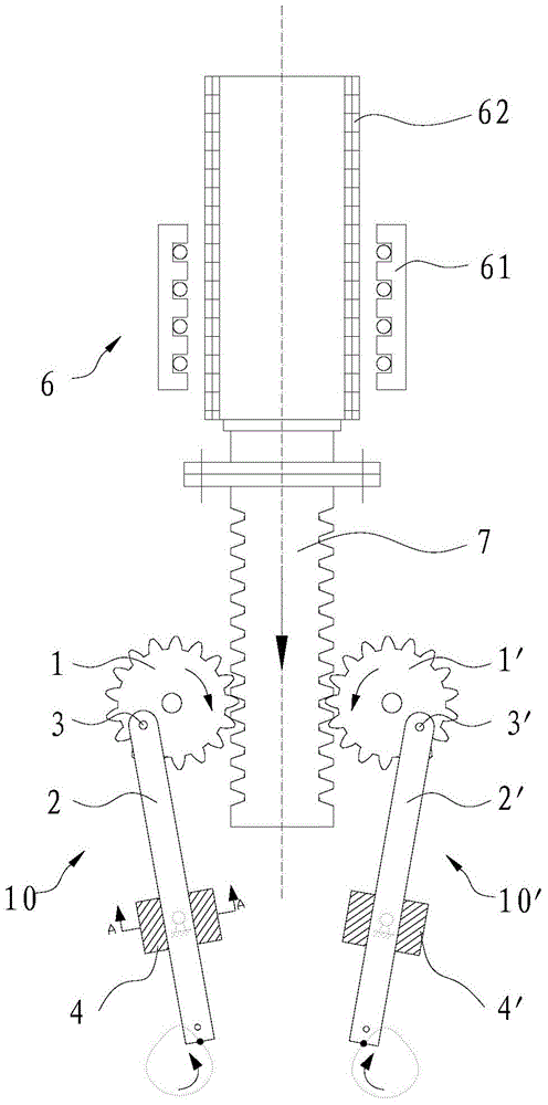
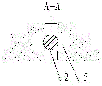
[0029] see picture 2 Shown electric hands rubbing bionic device, this bionic device and embodiment 1 The difference is mainly in the provision of connecting rod 2 、 2’ Settings for the oriented widget. In this embodiment, a connecting rod is provided 2 、 2’ The guiding part is the sliding seat 5, 5' hinged on the frame at the center, and the connecting line between the hinge points of the two axial ends of the sliding seat 5, 5' on the frame is parallel to the gear 1 、 1’ axis line. Sliding seats 5 and 5' are provided with connecting rods respectively 2 、 2’ Penetrating through hole, connecting rod 2 、 2’ The through holes on the sliding seats 5 and 5' are respectively loosely fitted, and the connecting rods 2、 2' and sliding seat 5, 5' form a plane low pair, when the rack 7 Moves along the length while driving the gear 1 ,gear 1’ When rotating, the connecting rod 2 、 2’ pin 3 、 3’ Under the action of sliding seat 5, 5', both l...


PUM


Abstract

The invention discloses an electric hands-rubbing bionic device, which comprises a frame, a linear motor arranged on the frame, a rack whose end part is connected to the secondary phase of the linear motor by transmission, and two sets of gears respectively arranged on both sides of the rack. Kneading components, each group of kneading components includes a gear, a connecting rod with one end eccentrically arranged on the gear, a cylinder or a sliding seat whose center is hinged on the frame, and a hole for the connecting rod to penetrate is opened on the cylinder or sliding seat. Holes and connecting rods are arranged in the above-mentioned through holes in a clearance fit, and the gears on the two groups of kneading components are respectively engaged with the racks. When the linear motor is working, the racks are driven to move along the straight line, and the gears can be driven to rotate, thereby The drive connecting rod performs both linear sliding motion and swing relative to the hinge support center of the cylinder or the sliding seat, and the lower end of the connecting rod can produce a bionic motion similar to human kneading, and kneading tools with different functions are fixed at the lower end of the connecting rod , can form a variety of electric hands rubbing bionic devices with different functions.

Description

technical field [0001] The invention relates to an electric bionic device for rubbing hands. Background technique [0002] At present, in the fields of production and life such as industry, medical treatment, and agriculture, there is an urgent need for a simple, practical, and low-cost hands-rubbing mechanism. For example, kneading and stirring powdery and lumpy materials in industrial production, hand massage in medical equipment, kneading tea leaves (mainly Biluochun) in agricultural production, kneading noodles in food production, etc. [0003] However, in the innovative design of the mechanism, it is extremely difficult to imitate the movement of human hands by relying solely on the movement of the mechanism itself. Because the movement of human hands rubbing is a compound motion of linear motion and swing. Using numerical control technology to imitate the action of human rubbing is the easiest technical solution to think of. However, using numerical control technolo...

Claims


Application Information

Patent Timeline
Patent Type & Authority Patents(China)
IPC IPC(8): F16H37/12H02K7/116
CPCF16H37/122F16H37/126H02K7/116
Inventor 王传洋窦云霞钟康民
Owner SUZHOU UNIV
Why Eureka
Try Eureka