Power station boiler hydraulic power soot blower

A technology of soot blowing device and power station boiler, which is applied in lighting and heating equipment, etc., can solve problems such as load limitation or even shutdown, affecting boiler economy and safety, and coking of furnace water walls.

Inactive Publication Date: 2014-01-08
单志贤
View PDF0 Cites 0 Cited by
  • Summary
  • Abstract
  • Description
  • Claims
  • Application Information

AI Technical Summary

Problems solved by technology

However, with the improvement of boiler parameters, the heat load of the furnace section is increasing, and the possibility of coking of the water wall of the furnace increases accordingly, which seriously affects the economy and safety of boiler operation, causing the unit to sometimes have to limit the load or even shut down. If serious coke loss occurs, it will also endanger the safety of the unit operators. However, the current use rate of sootblowers in my country is low, and they have not been able to fully play their role. Finding out the problem and solving it is our country's solution to sootblowing. The primary issue of device quality

Method used


Image

  • Power station boiler hydraulic power soot blower

Examples


Embodiment Construction

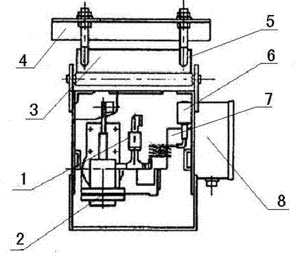
[0008] Depend on figure 1 As we know, the hydraulic soot blowing device of the power plant boiler is composed of a spray gun 1, a spray gun angle control system 2, a water pump 3, a valve 4, a semi-telescopic soot blower 5 and a control cabinet 6. The spray gun 1 is equipped with a one-way air valve 7, which is semi-telescopic. There is a valve 8 on the bottom side of the tail of the type soot blower, and the opening and closing mechanism of the valve is set on the valve 8. The opening and closing mechanism of the valve is connected with the one-way air valve 7. With cold water as the medium, it can clean the area of ​​nearly 500m2 of the furnace at one time during work. When installing each hydraulic soot blower, it is only necessary to open a 0.4m square hole in the water cooling wall, and the water blowing trajectory is controlled by software design during soot blowing.


PUM


Abstract

The invention provides a power station boiler hydraulic power soot blower. The power station boiler hydraulic power soot blower comprises a spray gun, a spray gun angle control system, a water pump, a valve, a semi-retractable soot blower body, a control cabinet and the like. A one-way air valve is arranged in the spray gun, wherein the valve is arranged on the bottom side of the tail portion of the semi-retractable soot blower body, and a valve opening and closing mechanism is arranged on the valve and connected with the one-way air valve. The power station boiler hydraulic power soot blower is characterized in that cold water is used as a medium, and coke in an area which is nearly 500 m<2> of a hearth can be cleaned at a time when the power station boiler hydraulic power soot blower operates; when the power station boiler hydraulic power soot blower is installed, only a 0.4 m<2> hole needs to be formed in a water wall, and a waterflow sweeping trajectory at the time of soot blowing is designed and controlled through software. The power station boiler hydraulic power soot blower can realize trajectory control over a water column through control over water quantity, water column diameter, water column speed, water column vertical adjustment angles and water column horizontal adjustment angles.

Description

technical field [0001] The invention relates to a large power plant boiler, especially a hydraulic soot blowing device for a power plant boiler. Background technique [0002] With the progress of the times, modern large-scale power plant boilers are developing in the direction of large capacity and high parameters. However, with the improvement of boiler parameters, the heat load of the furnace section is increasing, and the possibility of coking of the water wall of the furnace increases accordingly, which seriously affects the economy and safety of boiler operation, causing the unit to sometimes have to limit the load or even shut down. If serious coke loss occurs, it will also endanger the safety of the unit operators. However, the current soot blowers in my country have a low commissioning rate and cannot fully play their role. Finding out the problem and solving it is our country's solution to soot blowing. The primary issue of device quality. [0003] Hydraulic sootblo...

Claims


Application Information

Patent Timeline
Patent Type & Authority Applications(China)
IPC IPC(8): F23J1/00
Inventor 单志贤
Owner 单志贤
Why Eureka
Try Eureka