Oil-immersed transformer for wind turbine system

A technology for wind power generation systems and oil-immersed transformers, applied in the field of power transformers, can solve the problems of increasing the volume of transformers in wind power generation systems, inconvenient transformer safety protection and wiring, and increasing operating costs of wind power generation systems, achieving compact structure, The effect of small footprint and convenient wiring

Inactive Publication Date: 2014-01-08
四川风发电气科技有限公司
View PDF5 Cites 3 Cited by
  • Summary
  • Abstract
  • Description
  • Claims
  • Application Information

AI Technical Summary

Problems solved by technology

Due to the large overall volume of the oil-immersed transformer with a voltage level of 35kV, it is generally not suitable to be placed indoors in the box-type substation, but installed outdoors in the box-type substation, which brings a lot of inconvenience to the safety protection and wiring of the transformer.
[0003]In addition, due to the structural problems of the oil-immersed transformer used in the existing wind power generation system, the transformer cannot be drawn from the changed voltage to provide excitation and The required voltage for control requires another transformer for the wind power generation system. The self-use transformer transforms the voltage obtained by the aforementioned oil-immersed transformer to obtain a voltage suitable for the excitation and control requirements of the wind power generation system. Provide the voltage to the wind power generation system to ensure the normal operation of the wind power generation system
This not only greatly increases the operating cost of the wind power generation system, but also further increases the volume of the transformer in the wind power generation system, which brings a series of difficulties to installation, protection and other operations, which is extremely impractical
[0004] In order to reduce the volume of the oil-immersed transformer, the Chinese patent document discloses a "combined transformer" (publication number: CN 201146338, publication date: November 5, 2008 Japan), this technology is to arrange the oil tank, high-voltage chamber and low-voltage chamber of the transformer in the shape of "product" (the oil tank is in front, and the high-voltage chamber and low-voltage chamber are arranged behind the oil tank). Although it has compacted the structure of the transformer, To a certain extent, the size of the transformer is reduced and the footprint is reduced, but its size is still large, which is not conducive to its volume control

Method used


Image

  • Oil-immersed transformer for wind turbine system
  • Oil-immersed transformer for wind turbine system
  • Oil-immersed transformer for wind turbine system

Examples


Embodiment 1

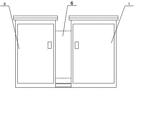
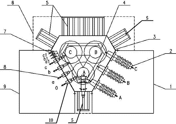
[0028] see Figure 1 to Figure 5 : the present invention comprises fuel tank 3, device body 4, high pressure chamber 1, low pressure chamber 9 and radiator 5.

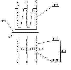
[0029] Wherein, the oil tank 3 is used to hold the transformer oil, and the device body 4 is installed. The horizontal section of the oil tank 3 is in the shape of a hexagon, and has three long sides of equal length. The short sides, these three short sides are connecting plates 3-4, and the three connecting plates 3-4 are respectively spaced between the high-voltage side panel 3-1, the low-voltage side panel 3-2 and the heat dissipation panel 3-3, that is, the three of the fuel tank 3 The long side and the three short sides are surrounded by each other, and the angle between the two long sides is 60° (equivalent to an equilateral triangle after chamfering). 120° rotational symmetry. A high-voltage bushing 2 is installed on the high-voltage side panel 3-1 of the fuel tank 3, and the high-voltage bushing 2 is connect...

Embodiment 2

[0034] The other structures of this embodiment are the same as those of Embodiment 1, the difference lies in: the horizontal section structure of the oil tank and the horizontal section structure of the high and low pressure chambers.

[0035] The horizontal section of the fuel tank is in the shape of an equilateral triangle, with each angle being 60° to form a high-pressure side panel, a low-pressure side panel and a heat dissipation panel. The horizontal section of the fuel tank is both axisymmetric and rotationally symmetric with a rotation angle of 120°.

[0036] The horizontal cross-sectional shapes of the high-pressure chamber and the low-pressure chamber are the same, which are respectively a right-angled trapezoidal shape, and the hypotenuses correspond to the respective assembly panels on the fuel tank.

[0037] The above-mentioned two embodiments are only two preferred specific technical solutions of the present invention, and the present invention can also make other...


PUM


Abstract

An oil-immersed transformer for a wind turbine system comprises an oil tank, a transformer body, a high-voltage chamber, a low-voltage chamber and a radiator. The oil tank is used for accommodating transformer oil, is arranged on the transformer body and comprises a high-voltage side face plate and a low-voltage side face plate. A high-voltage sleeve is arranged on the high-voltage side face plate, the high-voltage sleeve is connected with a high-voltage coil lead of the transformer body, and the high-voltage sleeve extends into a high-voltage chamber which is assembled and connected to the high-voltage side face plate. A low-voltage sleeve is arranged on the low-voltage side face plate, the low-voltage sleeve is connected with a low-voltage coil lead on the transformer body, and the low-voltage sleeve extends into a low-voltage chamber which is assembled and connected to the low-voltage side face plate. The radiator is assembled on at least one part of face plate of the oil tank except the high-voltage side face plate and the low-voltage side face plate. The included angle between the high-voltage side face plate and the low-voltage side face plate of the oil tank is an acute angle. The transformer body is of a double-winding or three-winding self-coupled three-dimensional roll iron core structure. The oil-immersed transformer for the wind turbine system is small in size and large in capacity, can effectively provide excitation and control required voltage for the wind turbine system and remarkably reduces transformer non-load loss and manufacturing cost.

Description

technical field [0001] The invention relates to a power transformer, in particular to an oil-immersed transformer used in a wind power generation system. Background technique [0002] Oil-immersed transformer is a transformer in which the core and winding body are immersed in insulating liquid. It is mainly composed of oil tank, body, high-voltage chamber, low-voltage chamber and radiator, etc., because of its good insulation performance and thermal conductivity. , heat dissipation performance and low operating cost. In recent years, it has been widely used in the rapidly developing wind power generation system. The oil-immersed transformer used in the wind power generation system is usually 35kV voltage level. Due to the large overall volume of the 35kV oil-immersed transformer, it is generally not suitable to be placed indoors in the box-type substation, but installed outdoors in the box-type substation, which brings a lot of inconvenience to the safety protection and wiri...

Claims


Application Information

Patent Timeline
Patent Type & Authority Applications(China)
IPC IPC(8): H01F27/14H01F27/30H01F27/40F03D11/00
CPCY02E10/722Y02P70/50
Inventor 丁友源
Owner 四川风发电气科技有限公司
Why Eureka
Try Eureka