
Environmental protection type low noise extrusion structure for separating water and sludge
An environment-friendly, water-separating technology, applied in filtration separation, separation methods, chemical instruments and methods, etc., can solve problems such as poor stability, pollution of force-applying devices, loud noise, etc., achieve fast compression and stretching speed, and avoid noise , the effect of low noise
Patent Information
- Authority / Receiving Office
- CN · China
- Current Assignee / Owner
- Publication Date
- 2014-01-15
- Estimated Expiration
- Not applicable · inactive patent
Smart Images
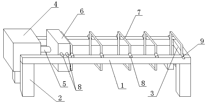
Figure 1
Abstract
Description
technical field
[0001] The invention relates to the field of waste water treatment, in particular to an environment-friendly low-noise extrusion structure for separating water and sludge. Background technique
[0002] In industrial production or life, a lot of waste water will inevitably be produced, and there are usually some harmful substances in the waste water. If it is discharged directly without treatment, it will have an adverse impact on the surrounding environment. Therefore, from the perspective of protecting the environment, wastewater must be treated before being discharged. Wastewater treatment mainly uses physical, chemical and biological methods to treat wastewater, purify wastewater, reduce pollution, and achieve the purpose of recycling and reusing wastewater and making full use of water resources. In wastewater treatment, physical treatment is usually used for pretreatment. Taking high-concentration organic wastewater as an example, micro-electrolysis tech...
Examples
Embodiment
[0019] Such as figure 1 As shown, this embodiment includes two cross bars 1 parallel to each other and four columns 2 supporting the two cross bars 1, one end of the two cross bars 1 is fixedly connected by a cross plate 3, and the other ends of the two cross bars 1 The cylinder 4 is fixed, and the front end of the piston rod 5 of the cylinder 4 is fixed with a top plate 6. At least one roller 8 is arranged on each side of the top plate 6. The top plate 6 is stuck between two cross bars 1 through the rollers 8 on both sides. .
[0020] Several brackets 7 are arranged between the two cross bars 1 of the present embodiment, the bracket 7 closest to the cross plate 3 is fixed on the cross bar 1 by bolts 9, and two rollers 8 are arranged on each other bracket 7, The bracket 7 is clamped between the two cross bars 1 by the roller 8, and the bracket 7 closest to the top plate 6 is fixedly connected with the top plate 6 .
[0021] The shape of the bracket 7 in this embodiment is sq...