Cutting blade and milling tool using same

A technology for cutting blades and blades, which is applied in the manufacture of tools, milling cutters, and milling machine equipment. It can solve the problems of limited profiling cutting capabilities, difficult control of cutting edge vibration, and difficulty in ensuring processing quality, so as to achieve small processing vibration and smooth processing. Both accessibility and simple structure

Active Publication Date: 2014-01-15
XIAMEN GOLDEN EGRET SPECIAL ALLOY
View PDF5 Cites 17 Cited by
  • Summary
  • Abstract
  • Description
  • Claims
  • Application Information

AI Technical Summary

Problems solved by technology

However, since the cutting edge 107 of the circular blade is arc-shaped, the forces on the margins are uneven, and the difference is large. The tool needs a fastener with a large diameter to provide a larger clamping force. Therefore, the mounting hole 109 of the circular blade generally has a larger radius. There must be enough space between the holes 109, so the arc radius of the cutting edge of the circular insert is generally large, and its profiling cutting ability is greatly limited
Generally, the arc radius of the cutting edge of the circular insert is more than 3mm, and it is impossible to process the curved surfa

Method used


Image

  • Cutting blade and milling tool using same
  • Cutting blade and milling tool using same
  • Cutting blade and milling tool using same

Examples


Embodiment 1

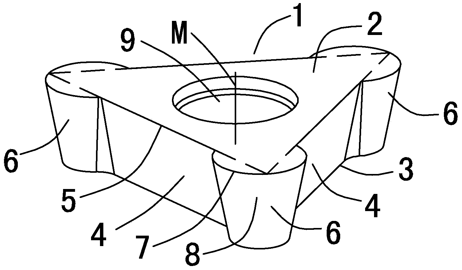
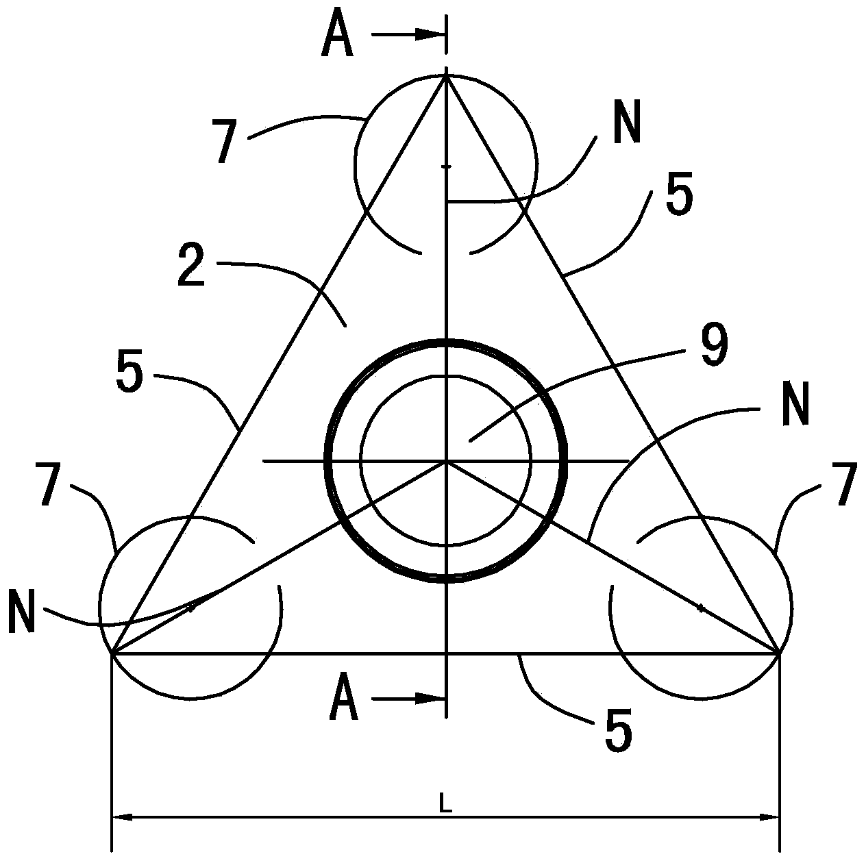
[0035] see Figure 2 to Figure 8 As shown, a kind of cutting insert of the present invention, this cutting insert forms positive type insert body 1 with hard material such as cemented carbide, and its shape is slightly equilateral triangular plate shape, and wherein upper surface 2 and lower surface 3 are parallel to each other, and lower surface 3 as a support surface, the side 4 connects the upper surface 2 and the lower surface 3, and the side 4 intersects with the upper surface 2 to form three perimeters 5. In the center of the upper surface 2 and the lower surface 3, a blade body 1 is formed vertically along the thickness direction. The installation hole 9 passing through the upper surface and the lower surface 3 forms an arc portion 14 on the installation hole 9, and the arc portion 14 is a contact area where the tapered portion of the clamping screw 11 presses the cutting insert. In addition, an outwardly protruding arcuate portion 6 relative to the insert mounting hole...

Embodiment 2

[0039] see Figure 9 to Figure 12 As shown, a cutting insert of the present invention differs from Embodiment 1 in that the side surface 4 and the upper surface 2 form an included angle α=90°, and the flank 8 of the cutting edge forms an angle with the upper surface 2 The included angle β=90°, the arc convex part also intersects with the lower surface to form a second arc-shaped cutting edge 71 protruding outward relative to the periphery, and each of the second arc-shaped cutting edges 71 passes through the lower surface 3 Corresponding vertices of the equilateral triangle formed by the line of intersection with the side and its extension. Like this, this cutting blade just has three first circular-arc cutting edges 7 and three second circular-arc cutting edges 71, and the shape structure of the first circular-arc cutting edge 7 and the second circular-arc cutting edge 71 same. Taking the first arc-shaped cutting edge 7 as an example, the chip breaker near the first arc-sha...


PUM


Abstract

The invention discloses a cutting blade and a milling tool using the same. The cutting blade comprises a cutting blade body, which is slightly in a regular triangle plate shape and comprises an upper surface, a lower surface, and side surfaces, which connect the upper surface and the lower surface; the positions between two neighbored side surfaces are individually provided with an arc protruded part relative to the center of the cutting blade, each arc protruded part intersects with the upper surface and forms a protruded first arc cutting blade relative to the circumstance, and each first arc cutting edge forms corresponding summits of a regular triangle through the intersection line between the upper surface and each side surface, and the extension line of the intersection line. The cutting blade and the milling tool using the same has the characteristics of strong profile copying performance, good economy, convenient installation, high positioning precision, large clamping force, and high processed surface quality.

Description

technical field [0001] The invention relates to the field of metal cutting tools, in particular to a milling tool used for profiling cutting materials and a cutting insert detachably mounted on the milling tool. Background technique [0002] In profiling cutting, since the surface to be machined is almost always a curved surface structure, the cutting edge of the cutting insert is required to be an arc edge, and the radius of the arc edge of the cutting insert must be smaller than the arc radius of the machined surface. In this way, the radius of the arc edge directly affects the profiling cutting ability of the blade. In general, the smaller the radius of the arc edge, the stronger the profiling cutting ability of the cutting insert and the wider the application range. [0003] In profiling cutting, circular inserts are generally used, figure 1 It is a cutting insert for profiling in the prior art. The insert body 100 is roughly in the shape of a conical plate, including ...

Claims


Application Information

Patent Timeline
IPC IPC(8): B23C5/20B23C5/08
Inventor 彭仕昌张冰冰邹伶俐张守全
Owner XIAMEN GOLDEN EGRET SPECIAL ALLOY
Why Eureka
Try Eureka