Well drilling device and method for controlling bottom hole pressure by monitoring flow

A technology for bottom-hole pressure and flow monitoring, applied in wellbore/well components, earth-moving drilling, flushing wellbore, etc. The effect of convenient automatic control, reduction of control objects, and reduction of equipment costs

Active Publication Date: 2014-01-15
BC P INC CHINA NAT PETROLEUM CORP +1
View PDF7 Cites 25 Cited by
  • Summary
  • Abstract
  • Description
  • Claims
  • Application Information

AI Technical Summary

Problems solved by technology

However, wellhead overflow may be caused by uneven weighting of the drilling fluid; if the pressure of the standpipe drops, it may be a puncture of the drilling tool; caused by
Using traditional drilling methods, if leakage or overflow is found, the amount of leakage or overflow is

Method used


Image

  • Well drilling device and method for controlling bottom hole pressure by monitoring flow
  • Well drilling device and method for controlling bottom hole pressure by monitoring flow
  • Well drilling device and method for controlling bottom hole pressure by monitoring flow

Examples


Embodiment 1

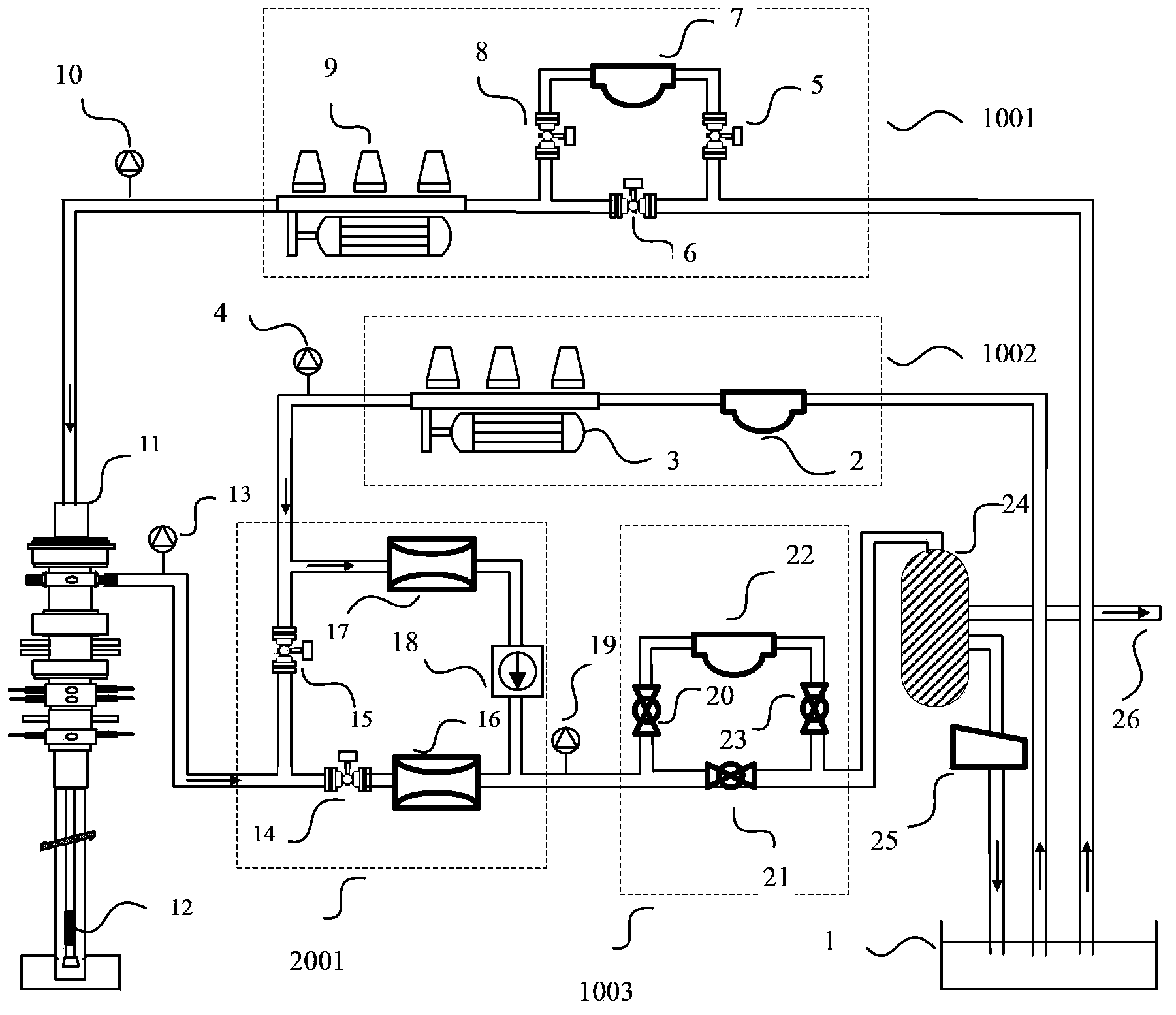
[0057] see figure 1 , a drilling equipment that uses flow monitoring to control bottomhole pressure, the equipment includes: mud pump inlet flow measurement system 1001, back pressure pump inlet flow measurement system 1002, drilling fluid return flow measurement system 1003, automatic throttle tube The sink system 2001, and the rotary control head 11, the liquid-gas separator 24, the vibrating screen 25, etc.; the dynamic sealing pressure of the rotary control head 11 is 14MPa, and the static sealing pressure is 35MPa; the back pressure pump 3 can be a 160 pump, and the rated working pressure is 35MPa , displacement: 12L / s; liquid-gas separator 24 liquid handling capacity: 200m 3 / h, gas handling capacity: 20000m 3 / h, working pressure: 1.5MPa.

[0058] Specifically, as a preference, the inlet of the mud pump inlet flow measurement system 1001 is connected to the mud tank 1 by a pipeline, and the outlet of the mud pump inlet flow measurement system 1001 is connected to the ...

Embodiment 2

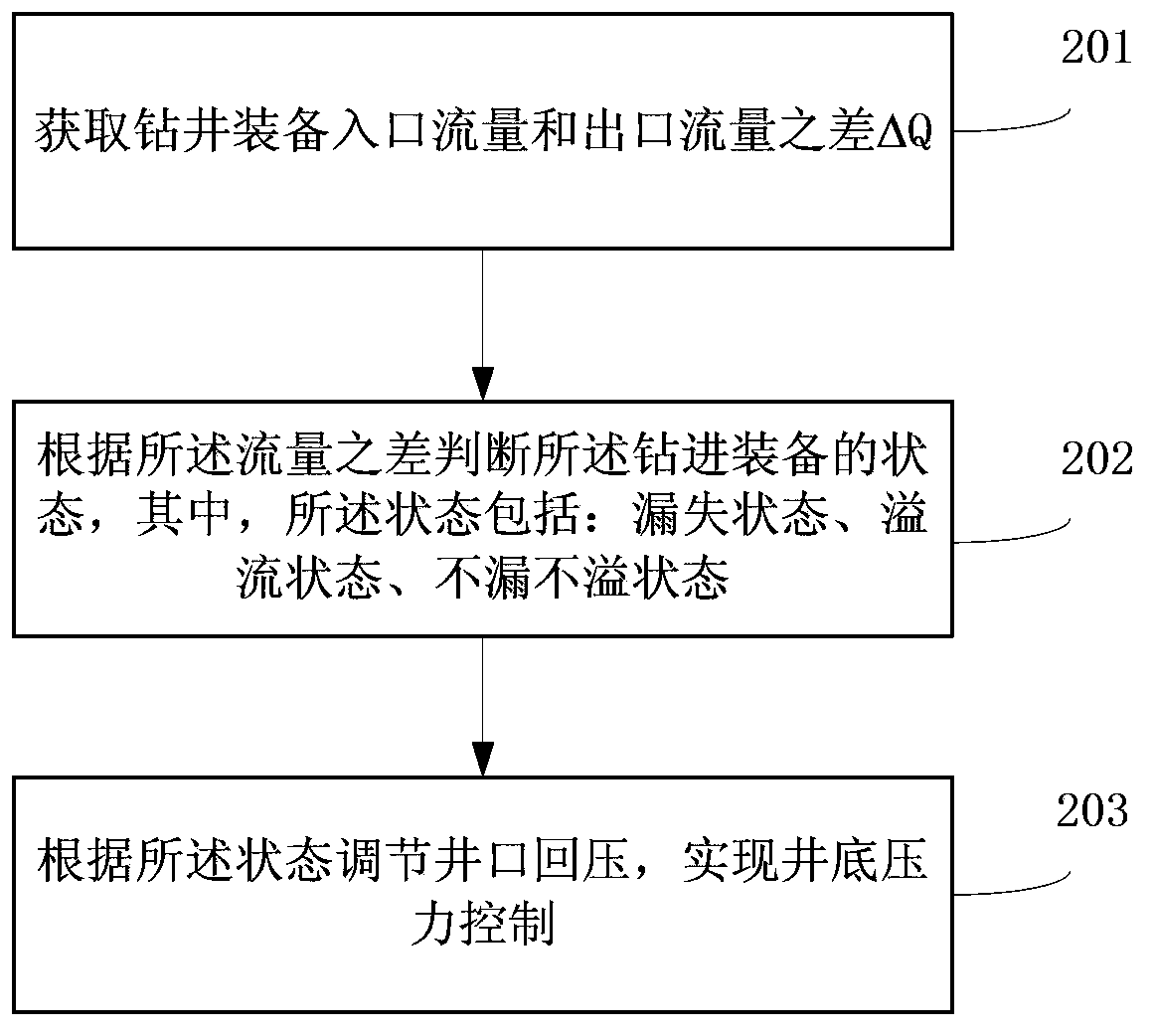
[0065] The present invention also provides a method for controlling the bottomhole pressure by using the flow monitoring of the drilling equipment described in Embodiment 1. During drilling, the drilling conditions are divided into three basic conditions: normal drilling, tripping, and single root connection , Tripping generally refers to the replacement of drilling tools. Lifting the drilling tools out of the ground from the ground is called "tripping". Bottom, called "drilling down", single connection generally means that during the drilling process, when the uppermost part of the kelly is about to reach the bushing and cannot continue drilling, the kelly needs to be lifted out, and then a kelly should be connected above the lower part of the kelly. In order to continue drilling down the drill pipe, the process of connecting only one drill pipe is called single connection.

[0066] Through analysis under different working conditions, it is judged that the equipment is in the...

Embodiment 3

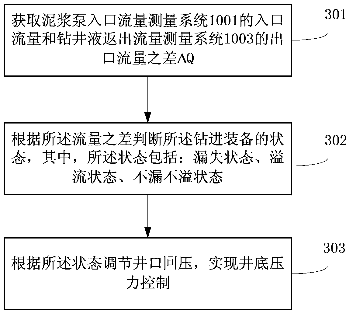
[0073] This embodiment provides a method for controlling the bottomhole pressure by using the flow monitoring of the drilling equipment described in the first embodiment. Combining with the content of the first embodiment above, this embodiment takes the normal drilling working condition as an example for illustration. Under normal drilling conditions, the drilling fluid is sucked from the mud tank 1, passed through the first manual plate valve 5, the second mass flow meter 7 and the third manual plate valve 8, and then pumped into the drill string through the mud pump 9, and the drilling fluid is pumped into the drill string by the drill pipe From the water hole to the bottom of the well, return to the ground from the wellbore annulus, blocked by the rotary control head 11, reversed and enter the automatic throttle manifold system 2001, pass through the first air control plate valve 14 and then pass through the first hydraulic throttle valve Throttle 16, enter the drilling flu...


PUM


Abstract

The invention discloses a well drilling device and method for controlling bottom hole pressure by monitoring flow. The well drilling device comprises a slime pump inlet flow measuring system, a return pressure pump inlet flow measuring system, a drilling liquid reversing-out flow measuring system, an automatic throttling pipe converging system, a rotation control head, a liquid-gas separator and a vibration screen. The inlet of the slime pump inlet flow measuring system is connected to a slime tank through a pipeline. The outlet of the slime pump inlet flow measuring system is connected to a drilling rod through a pipeline, reaches the rotation control head from a drill and a borehole by passing the bottom of the drilling rod in an annular space mode, and is communicated with an inlet pipeline of the automatic throttling pipe converging system and an outlet pipeline of the return pressure pump inlet flow measuring system. The return pressure inlet flow measuring system is connected to the slime tank through a pipeline. The outlet of the automatic throttling pipe converging system is connected with the inlet of the drilling liquid reversing-out flow measuring system. The outlet of the drilling liquid reversing-out flow measuring system is connected with the inlet of the liquid-gas separator through a pipeline. The liquid-gas separator is provided with two branches, wherein one branch is connected to the vibration screen and connected to the slime tank through the vibration screen and the other branch is connected to a combustion opening. The well drilling device and method for controlling the bottom hole pressure by monitoring the flow can effectively control or eliminate adverse affection on well drilling, wherein the adverse affection is caused by shaft bottom leakage and losses or overflowing which can cause.

Description

technical field [0001] The invention belongs to the field of oil and natural gas drilling pressure control systems, and relates to a drilling equipment and method for realizing bottom-hole pressure control by using flow monitoring. Background technique [0002] Loss and overflow are downhole complex situations that are often encountered in the drilling process. Among them, leakage refers to a downhole complex situation in which drilling fluid leaks into the formation during oil and gas drilling engineering operations. On the one hand, it directly leads to the loss of a large amount of drilling fluid and affects normal drilling. During operation, the well wall may even become unstable due to the excessive drop in fluid column pressure, leading to well collapse or even sticking, and the scrapping of some or all well sections. It will cause serious damage to the reservoir; and overflow refers to a complex downhole situation in which formation fluid flows into the wellbore durin...

Claims


Application Information

Patent Timeline
IPC IPC(8): E21B21/08
Inventor 石林刘伟周英操方世良王瑛赵庆杨雄文罗良波王凯郭庆丰翟小强朱卫新
Owner BC P INC CHINA NAT PETROLEUM CORP
Why Eureka
Try Eureka