Layered oil exploitation device

A technology of layered oil production and hydraulic switch, which is applied to the valve device of wellbore/well, production fluid, earth-moving drilling and other directions, can solve the problem that the tool cannot be reversed, and achieves the reduction of labor intensity and operation cost, and the simple structure. , the effect of strong operability

Active Publication Date: 2014-01-15
东营市金宇石油机械有限责任公司
View PDF7 Cites 25 Cited by
  • Summary
  • Abstract
  • Description
  • Claims
  • Application Information

AI Technical Summary

Problems solved by technology

Mechanical layering devices also appeared in the later period, but the problem is that the tool cannot achieve reversing
The existing problem is: the tool cannot achieve reversing

Method used


Image

  • Layered oil exploitation device
  • Layered oil exploitation device
  • Layered oil exploitation device

Examples


Embodiment 1

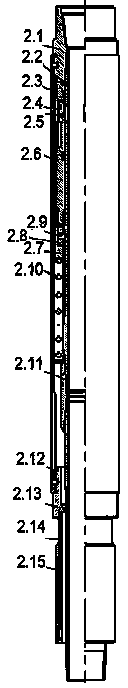
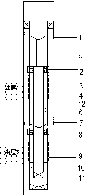
[0018] Embodiment 1: in combination with Figure 1-3 , the present invention is taken as the example of two layers with the horizon of oil layer, and the present invention is further described:

[0019] The present invention includes a first packer 1, a first hydraulic switch 2, a first sand control pipe 3, a center pipe 4, an oil pipe 5, a first mechanical sliding sleeve 6, a second packer 7, a second hydraulic switch 8, a first The second sand control pipe 9, the second mechanical sliding sleeve 10, the blind plug 11 and the outer pipe 12 divide the oil well into two sections through the first packer 1, the upper section is the liquid production part, and the lower section is the liquid supply part, and the liquid supply part includes First hydraulic switch 2, first sand control pipe 3, central pipe 4, oil pipe 5, first mechanical sliding sleeve 6, second packer 7, second hydraulic switch 8, second sand control pipe 9, second mechanical sliding sleeve 10. Blind plugging...

Embodiment 2

[0028] Example 2: When the oil layer has three layers, the first sand control pipe 3 and the second sand control pipe 9 can be respectively arranged at the corresponding oil layer, between the first packer 1 and the first sand control pipe 3 A first hydraulic switch 2 is provided to form the first layer liquid supply system; a second hydraulic switch 8 is provided between the second packer 7 and the second sand control pipe 9 to form the second layer liquid supply system; A third hydraulic switch is installed between the third packer and the third sand control pipe to form the third layer liquid supply system; to realize the separate exploitation of the three oil layers, and the track is also different according to the number of oil layers. Adjust accordingly. By analogy, when the layers of the oil layer are four layers, corresponding adjustments are also made, and the equivalent transformation of its structure is within the protection scope of the present invention.


PUM


Abstract

The invention relates to an oil exploitation device, in particular to a layered oil exploitation device. The layered oil exploitation device comprises a first packer, a first hydraulic selector, a first sand-proof pipe, a central pipe, an oil pipe, a first mechanical sliding sleeve, a second packer, a second hydraulic selector, a second sand-proof pipe, a second mechanical sliding sleeve, a blind plug and an outer pipe. An oil well is divided into two sections through the first packer, the upper section is a liquid withdrawal part, and the lower section is a feed flow part. A plurality of layered feed flow systems are arranged according to the number of oil layers, and respective exploitation of layer positions of a plurality of oil layers is achieved. The layered oil exploitation device has the advantages that (1) a tubular column can achieve the construction of oil production by layer and repeated reversing, working procedures are greatly reduced, labor intensity is reduced, working cost is reduced, and construction period is shortened; (2) the layered switches are controlled by pressing the outer pipe, the control over the oil layers is achieved, and the layered oil exploitation device is easy and convenient to use.

Description

technical field [0001] The invention relates to an oil recovery device, in particular to a layered oil recovery device. Background technique [0002] In oil field production, multi-level is a common phenomenon. In many layers, the oil-water content of liquid is different. In order to improve efficiency, in oil field production, it is necessary to inject ash, water shut-off agent, chemical water shut-off Block the water layer and exploit the oil layer in other ways to increase the oil recovery rate, reduce the cost and increase the benefit. A mechanical layering device also appeared in the later period, but its existing problem is that the tool cannot realize reversing. The Chinese patent publication number is CN102839950A, which discloses "A Kind of Oil Well Layered Production Process String", which is composed of oil pipe, pipe string feeding tool, FCA packer, FCB packer, FCC recovery basket, and bridge plug. The method consists in tightening the oil production string...

Claims


Application Information

Patent Timeline
Patent Type & Authority Applications(China)
IPC IPC(8): E21B43/14E21B34/06
Inventor 王志强
Owner 东营市金宇石油机械有限责任公司
Why Eureka
Try Eureka