An energy-saving heat pump dehumidification drying room and its control method

A control method and an energy-saving technology, applied in the field of baking rooms, can solve the problems of energy waste, large energy consumption, and unrecyclable heat energy, and achieve the effects of reducing energy consumption, avoiding excessive moisture removal, and reducing temperature loss.

Active Publication Date: 2016-03-23
JIANGMEN HUAYAN AUTOMATION EQUIP +1
View PDF7 Cites 2 Cited by
  • Summary
  • Abstract
  • Description
  • Claims
  • Application Information

AI Technical Summary

Problems solved by technology

Compared with the traditional coal-heated drying room, the heat pump drying room is more environmentally friendly and energy-saving, and can adapt to the requirements of different drying processes. However, most of the drying rooms with this structure use direct fans for dehumidification. Although the dehumidification effect is obvious, However, heat energy cannot be recycled, resulting in energy waste
In addition, when the structure is baked, the heat pump component is generally turned on first to work. When the humidity in the room reaches the dehumidification condition, the dehumidification fan is turned on to draw the air outside the room into the room, and at the same time pump out the high-temperature and high-humidity gas in the room. Outside the room, until the humidity in the room reaches the target value, stop dehumidification. In this control method, the heat pump component and the dehumidification fan run at full speed during the entire dehumidification process, which consumes a lot of energy.

Method used


Image

  • An energy-saving heat pump dehumidification drying room and its control method
  • An energy-saving heat pump dehumidification drying room and its control method
  • An energy-saving heat pump dehumidification drying room and its control method

Examples


Embodiment Construction

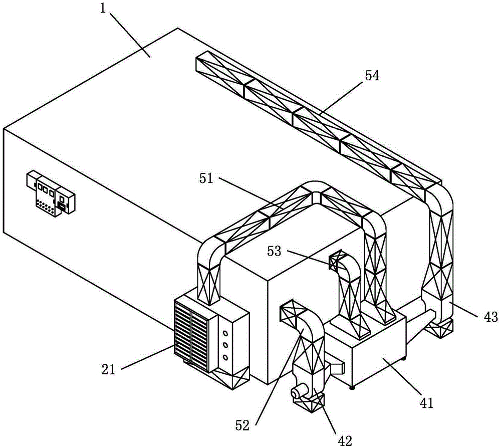
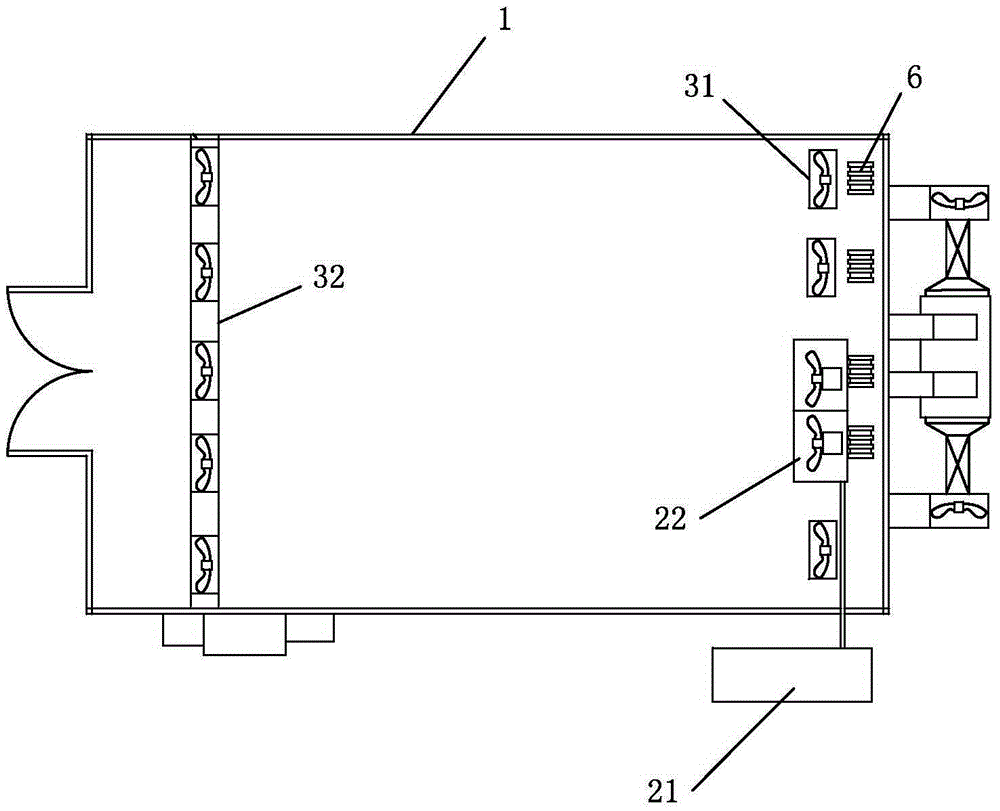
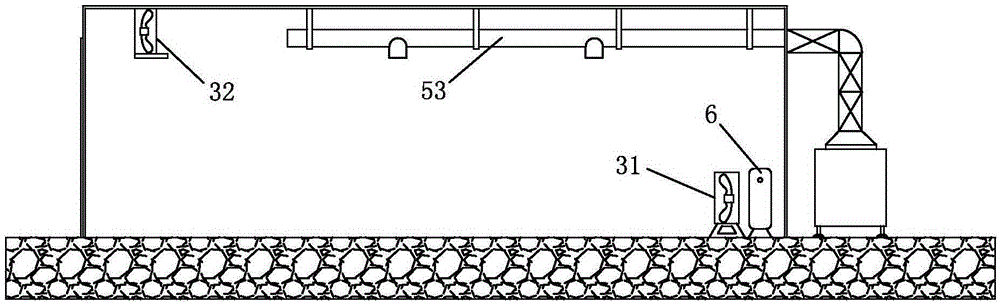
[0044] refer to Figure 1 to Figure 4, an energy-saving heat pump dehumidification drying room of the present invention includes a room body 1, a heat pump assembly, a circulating fan assembly and a dehumidification assembly. The heat pump assembly includes a heat pump main machine 21 arranged outside the house body 1 and a heat pump auxiliary machine 22 arranged inside the house body 1. The heat pump main machine 21 includes an evaporator, a throttling device, and a compressor, and the heat pump auxiliary machine 22 includes a condenser. The evaporator, compressor, condenser, and throttling device are sequentially connected through pipelines to form a circulation system; The heat exchanger 41 of non-direct contact convective heat exchange, the inside of the heat exchanger 41 is provided with a fresh air channel and a dehumidification channel that are not connected to each other, and the entrance of the fresh air channel is connected with a cold air pipeline 51 connected to th...


PUM


Abstract

The invention discloses an energy-saving heat pump humidity removing drying room and a control method of the drying room. The drying room comprises a room body, a heat pump assembly, a circulating fan assembly, a humidity removing assembly, a main control unit and a temperature and humidity sensor, wherein the humidity removing assembly comprises a heat exchanger, an air inlet fan and a humidity removing fan, and the air inlet fan and the humidity removing fan are respectively connected with an air regulator. When humidity removal is performed in the drying room, external air is turned into dry cold air through a heat pump host, the dry cold air enters the heat exchanger and is conveyed back into the room body after having non-direct-contact heat exchange with high-temperature and high-humidity air pumped out of the room body, and therefore energy is saved. The actual measured temperature and the actual measured humidity are compared with preset stage values, particularly, the preset stage values are divided into preset values in a shutting down stage and preset values in a starting stage, the starting stage is subdivided into a plurality of segments, firstly, the stage or the segment where the actual measured humidity is located is judged through the current humidity, then, according to the current temperature, the actual measured temperature is compared with the set temperature value in the stage or the segment, the humidity removing assembly is controlled to operate at low speed or to operate at full speed or to shut down, and therefore drying efficiency is improved, and energy consumption is reduced.

Description

technical field [0001] The invention relates to the field of baking rooms, in particular to an energy-saving heat pump dehumidification drying room and a control method thereof. Background technique [0002] The drying room is a kind of equipment for baking products, which is widely used in the processing of agricultural and sideline products. The traditional drying room mainly relies on coal furnace heating, and the hot air is blown to every corner of the room through the circulating fan, so as to realize the baking of the products in the room. Due to the use of coal for heating, this equipment not only consumes high energy consumption, The environment is seriously polluted, and the operation is cumbersome and labor-intensive. [0003] In order to solve the above problems, a heat pump drying room has appeared in recent years, which mainly includes an evaporator, a compressor, a condenser and a throttling device. Heat is released in the indoor drying room) → throttling → r...

Claims


Application Information

Patent Timeline
Patent Type & Authority Patents(China)
IPC IPC(8): F26B21/00F26B21/08F26B21/10F26B9/02
Inventor 邓延青
Owner JIANGMEN HUAYAN AUTOMATION EQUIP
Why Eureka
Try Eureka